TECHNICAL MANUAL
Chapter 9 - User - Control Interface
NGSi 05÷15
16
ENGLISH
EN
The data in this manual are not binding and they can be modified by the manufacturer without notice. Reproduction of this manual is strictly prohibited
9.2 Parameters category
9.3 Setpoints settable by the user
The second setpoint is only operational if the relative optional kit has been purchased.
9.4 Display
Normally, the display shows the water output temperature in tenths of a degree Celsius or the alarm code if at least one alarm has been
tripped. With several alarms present, the first one is shown and the second one appears after the first has been reset. In menu mode, the
contents of the screen depend on the function being used.
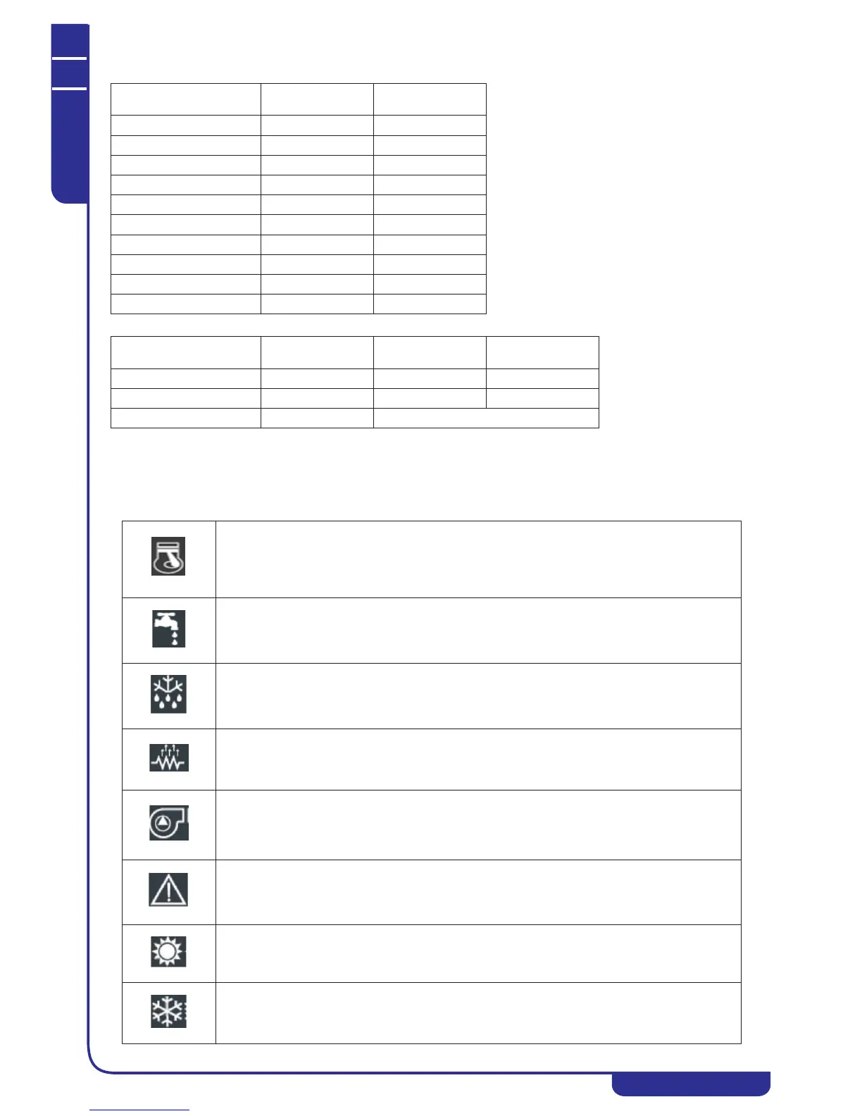
9.5 LEDs
Description
Group identification
code
Parameter index
Configuration
CnF H01-
Compressor
CP C01-
Fan
FAn F01-
Alarms
ALL A01-
Adjustment
Re b01-
Pump
PUP P01-
Electric heaters
Fro r01-
Defrosting
dFr d01-
Electronic valve
EEu U01-
Offset
OFF o01-
Setpoint type
Setpoint
(summer/winter)
Summer
default (range)
Winter
default (range)
First setpoint [°C]
Coo/Hea 7 (5÷18) 45 (35÷55)
Second setpoint [°C]
Co2/He2 18 (7÷23) 35 (25÷45)
Hot water setpoint [°C]
San 48 (25÷55)
Compressor LED • ON with compressor in operation.
• OFF with compressor not running.
• FLASHING if compressor start delay timer is running.
Domestic hot
water LED
• ON with domestic hot water valve active.
• OFF with domestic hot water valve not active.
Defrost LED • ON with defrosting active.
• OFF with defrosting disabled or completed.
• FLASHING if defrosting interval timer is running.
Antifreeze heater
LED
• LED ON with antifreeze heater (optional) in operation.
Pump LED • LED ON with pump in operation.
Alarm LED • LED ON with an alarm tripped.
Heating mode
LED
• LED ON with unit in heating mode.
Cooling mode
LED
• LED ON with unit in cooling mode.