TECHNICAL MANUAL
Chapter 9 - User - Control Interface
NGSi 05÷15
30
ENGLISH
EN
The data in this manual are not binding and they can be modified by the manufacturer without notice. Reproduction of this manual is strictly prohibited
In this way, the heat pump will stop at the setpoint set (G02, G03, G05) and the temperature difference, according to the offset set, will be
supported by the hot water tank and/or the heaters.
9.19 System season indication
It is possible to configure a digital output to indicate the season of operation of the machine, on system side (the digital outputs are 230V
AC, for this purpose they must therefore operate a relay not supplied with voltage-free contacts). The digital outputs are configured setting
to 31 the parameters H58 (230V AEH, AEHN output) or H61 (230V, NO1, N output) (for other outputs which can be used in the terminal
board and their configurations see Part 9.25). The output is active in summer operation, while in OFF or heat status it is disabled. During
domestic hot water operation, the output keeps the same setting of the season of origin.
9.20 Fan and dissipation control
The dissipation control depends on the condensing pressure in chiller mode, while it depends on the evaporation pressure in heat pump
mode.
The ventilation adjustment occurs in a way dependent on the compressor operation.
9.20.1 Ventilation control in chiller mode
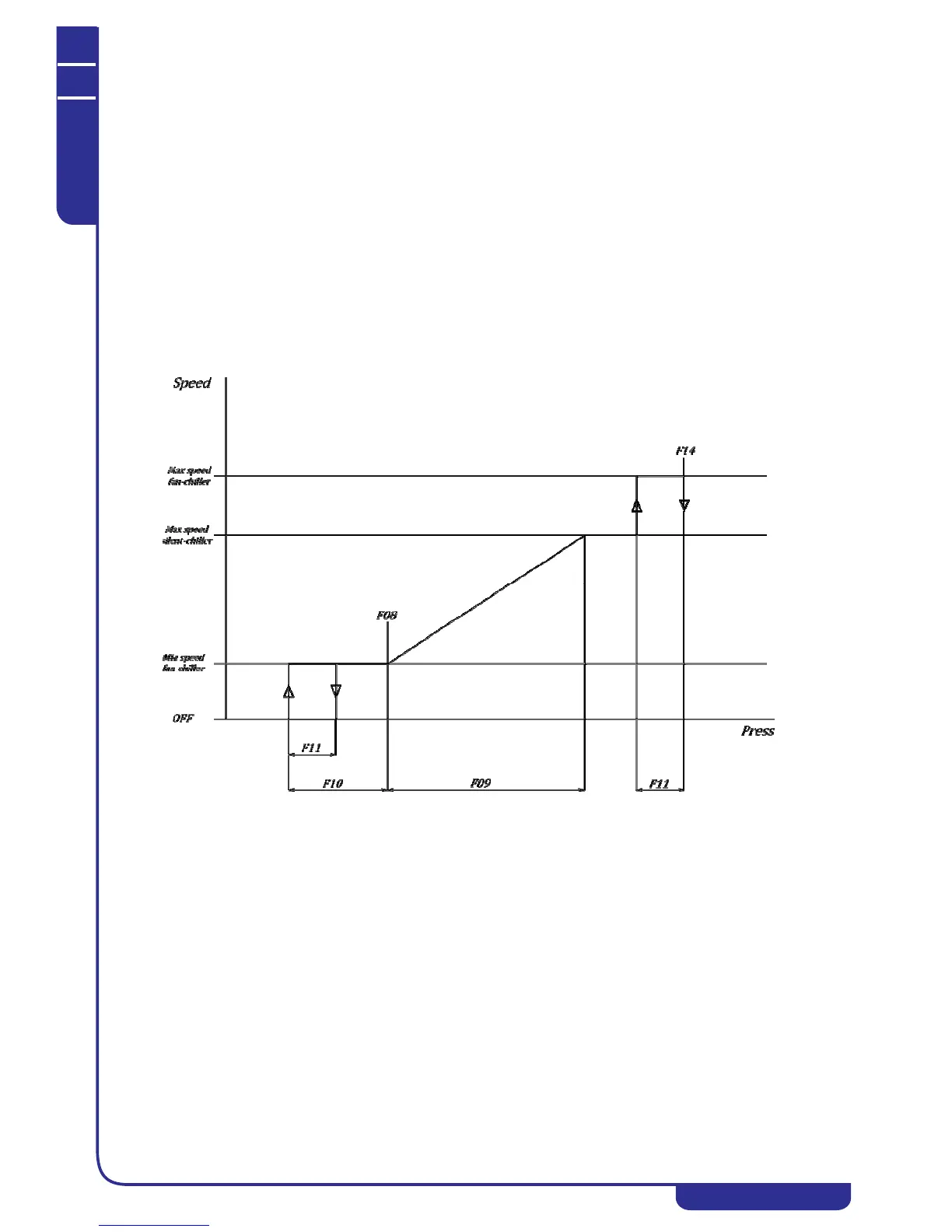
The ventilation control in chiller mode occurs according to the diagram shown below, where:
F08 = Pressure setpoint for the fan minimum speed in chiller mode
F09 = Fan proportional band in chiller mode
F10 = Fan delta cut-off in chiller/heating mode
F11 = Cut-off hysteresis in chiller/heating mode
F14 = Pressure setpoint for the fan maximum speed in chiller mode
In chiller mode a pre-ventilation period is active: before starting the compressor, the fan is turned on for 5 seconds; the fan speed is
proportional to the condensing temperature, however, if the controller requires the cut-off during this period, the fan will run at the minimum
speed set. This function prevents the compressor from starting with too high condensation temperatures.
9.20.2 Ventilation control in heating mode
The ventilation control in heat pump mode occurs according to the diagram shown below, where:
F17 = Pressure setpoint for fan minimum speed in heating mode
F18 = Fan proportional band in heating mode
F10 = Fan delta cut-off in chiller/heating mode
F11 = Cut-off hysteresis in chiller/heating mode
F20 = Pressure setpoint for fan maximum speed in heating mode