TECHNICAL MANUAL
Chapter 21 - Double setpoint kit (optional accessory)
NGSi 05÷15
51
ENGLISH
EN
The data in this manual are not binding and they can be modified by the manufacturer without notice. Reproduction of this manual is strictly prohibited
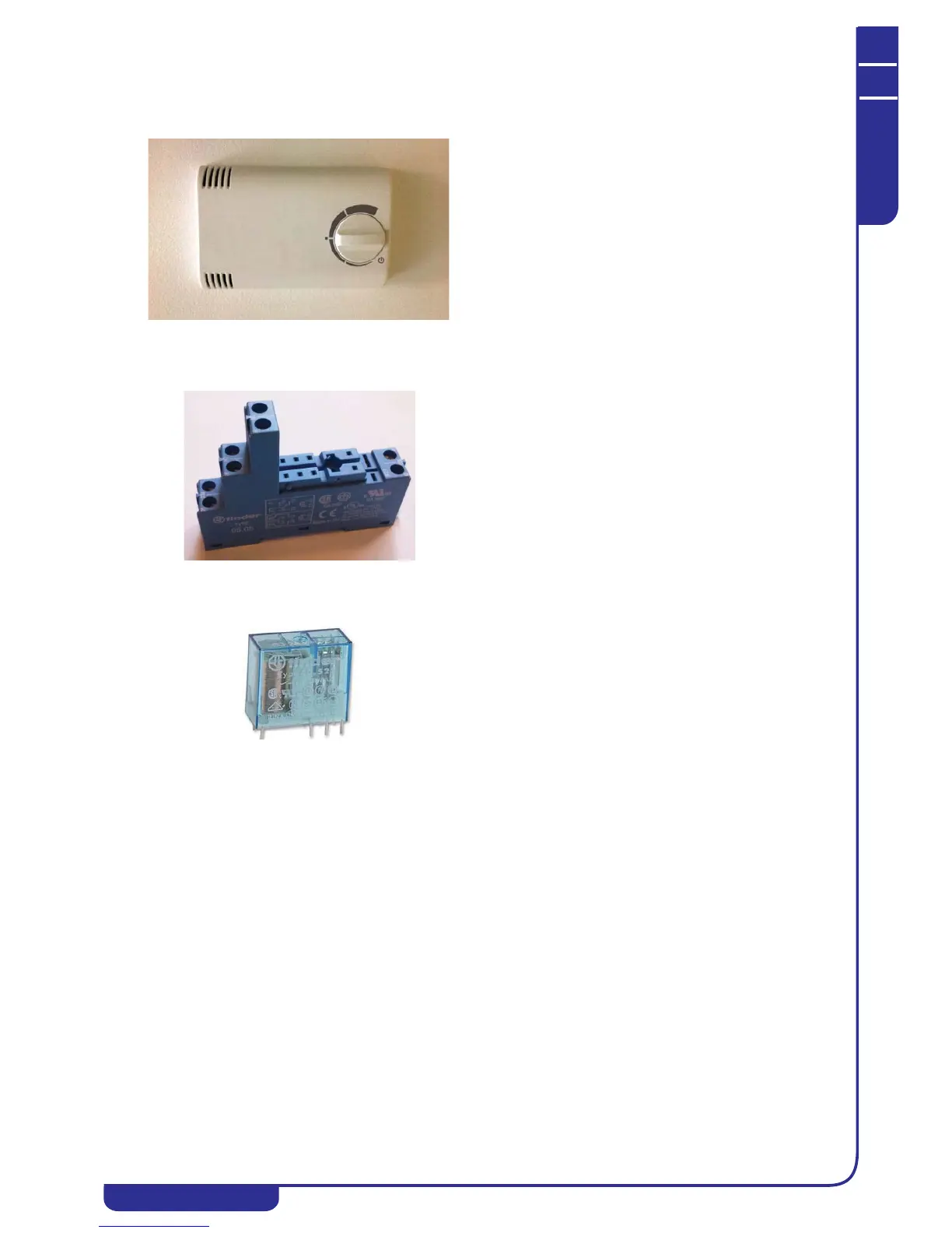
21.2 Kit components and technical data
Humidity switch
DIN bar socket
Relay
21.3 Humidity switch mode operation
The dewpoint is calculated by means of the internal temperature and humidity probe reading.
The room temperature measured by the probe inside the controller is compared with the dewpoint (calculated at the last moment of tAr)
added to parameters odr and Hy:
• if Tr<Tint<Tr+odr ĺ the relay is activated for the whole of the next time tAr
• if Tr+odr<Tint<Tr+odr+Hy ĺ the relay is activated for the % value of tAr selected on the ramp
• if Tint<Tr+odr+Hy ĺ the relay is deactivated for whole of the next time tAr
Parameters tAr, odr and Hy are set in the factory and cannot be modified.
• power supply 12-24 Vac
• internal temperature and humidity probe
• trimmer for setting an offset of -3 to +3°C in
relation to the dewpoint
• RS485 serial
• for application on DIN bar
• maximum current per pole: 10 A
• 230V DC power supply
• maximum resistive load per pole: 8 A
• maximum inductive load per pole: 1.6 A