AIR INTAKE SYSTEM
23
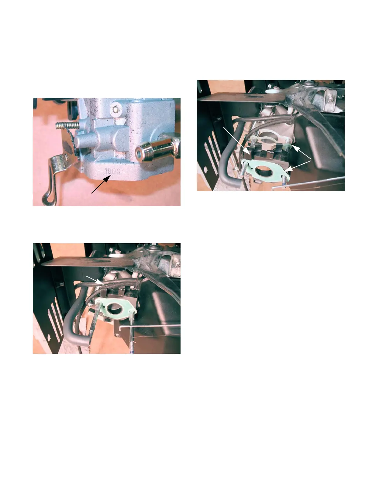
NOTE: The carburetors are not inter-changeable
from one engine model to another. To help pre
-
vent carburetor mix-ups, the engine model num-
ber is stamped on the carburetor by the fuel
nipple.
See Figure 3.6.
4. Unhook the ignition wires from the clip molded
into the insulator plate.
See Figure 3.7.
Figure 3.6
Engine model number
Spark plug wire
Clip
Figure 3.7
Ignition wires
NOTE: An insulator block separates the carbu-
retor from the cylinder head. There is a gasket
on each side of the insulator.
See Figure 3.8.
NOTE: The gaskets are different, and there is an
orientation to the insulator.
• The bowl vent channel in the insulator faces the
carburetor, with the exit toward the bottom.
• There is a small hole in the insulator to carbure-
tor gasket. The hole should be aligned to allow
passage of air through the bowl vent channel to
the throttle side bowl vent in the carburetor body.
5. Install the insulator and carburetor by following
the above steps in reverse order.
NOTE: Tighten the carburetor mounting nuts to
a torque of 80 - 106 in-lbs (9-12 Nm).
6. Test run the engine before returning to service.
Figure 3.8
Insulator block
Gaskets
 Loading...


