THE FUEL SYSTEM AND GOVERNOR
35
To install the governor arm:
1. Rotate the governor shaft clockwise until it
stops.
2. Slide the arm onto the shaft. The flat on the top
of the shaft should be roughly parallel to the arm.
See Figure 4.23.
NOTE: There is a hairpin clip that keeps the gov-
ernor shaft from sliding into the engine. It may be
necessary to hold the shaft while sliding the arm
on to prevent the hairpin clip from “popping off”
and allowing the governor shaft to fall into the
engine.
3. Tighten the nut on the clamp bolt to secure the
arm.
4. Attach the governor linkage and spring.
5. Adjust the governor to maintain top no-load
speed as described in a previous section of this
chapter.
Governor shaft
To remove or replace the governor shaft:
1. Remove the engine from the equipment that it
powers.
2. Remove the governor arm by following the previ-
ously described steps.
3. Remove the flywheel by following the steps
described in Chapter 7: Ignition Systems.
4. Remove the crank case cover and crankshaft
from the engine by following the steps described
in Chapter 10: Cam, Crankshaft and Piston.
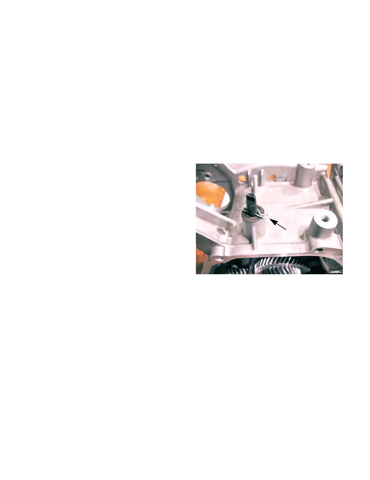
5. Remove the hairpin clip from the governor shaft.
See Figure 4.24.
6. Slide the governor arm out of the engine block
from the inside of the engine.
7. Check the movement of the fly-weights and cap
on the governor gear.
8. Install the shaft by following the above steps in
reverse order.
9. Install the engine on the equipment it powers.
10. Test run the engine and adjust the top no load
engine rpms by following the steps described in
the carburetor section of this chapter.
Figure 4.24
Remove
hairpin clip
 Loading...