13
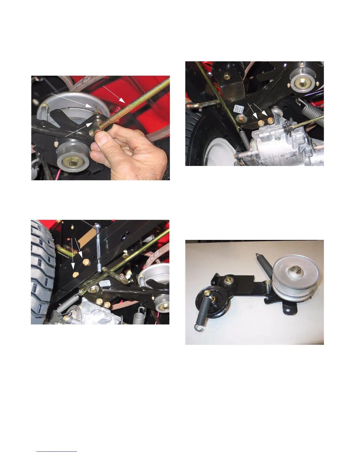
10.2. Remove the cotter pin securing the variable
speed control rod to the variable speed idler
bracket. Remove the ferrule from the bracket
and let the rod hang down out of the way. See
Figure 40.
10.3. Using a ½” socket, remove the two screws
securing the torque bracket to the frame. See
Figure 41.
NOTE: If you are using air tools you can remove
the right rear tire to gain better access to the hex
screws.
Figure 40
Variable Speed Control Rod
Ferrule
Cotter Pin
Figure 41
Hex Screws
10.4. Using a ½” socket, remove the two screws
securing the torque bracket to the transmission.
See Figure 42.
NOTE: Pivot the idler bracket away from the
transmission to allow better access to the
mounting screws.
10.5. Remove the torque bracket and variable speed
idler assembly from the unit.
10.6. Inspect all components of the variable speed
assembly. See Figure 43.
10.7. Replace any warn or damaged parts.
10.8. Lubricate all moving parts before assembly.
Figure 42
Torque Bracket Mounting Screws
Figure 43
Deck Hanger Bracket
www.mymowerparts.com
For Discount White Outdoor Parts Call 606-678-9623 or 606-561-4983