8
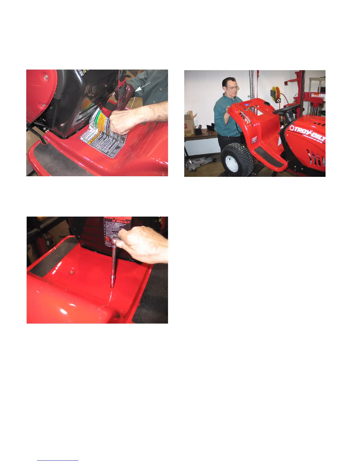
6.8. Using a heat gun, carefully heat the warning
label and peel it from the fender panel. Set it
aside to be re-installed during assembly. See
Figure 23.
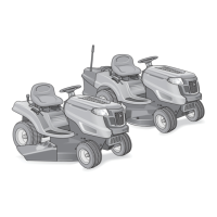
6.9. Using 3/8” socket, remove the two screws secur-
ing the center section of the fender to the frame.
See Figure 24.
6.10. Remove the shifter knob, deck lift grip, and deck
engagement grip.
NOTE: You can use an air gun placed in the hole
at the top of each grip to ease disassembly.
6.11. Lift up on the rear of the fender to clear the seat
support springs, slide the fender towards the
rear and remove it from the tractor. See Figure
25.
NOTE: During removal, slip the seat safety
switch wires through the hole in the fender.
Remember to route these wires through the
same hole during assembly.
7. UPPER DRIVE BELT REMOVAL
NOTE: It is recommmended that both the upper
and lower drive belts be replaced as a set.
7.1. Tip the seat forward.
7.2. Disconnect the battery cables, remove the bat-
tery and the battery tray from the unit.
Figure 23
Heat Gun
Figure 24
Figure 25
www.mymowerparts.com
For Discount White Outdoor Parts Call 606-678-9623 or 606-561-4983