6
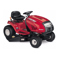
5.4. Using an impact wrench and a 15/16” socket
remove the pulley and blade from the spindle
assembly. See Figure 15.
NOTE: Use a blade stop to secure the blade and
prevent it from rotating during disassembly.
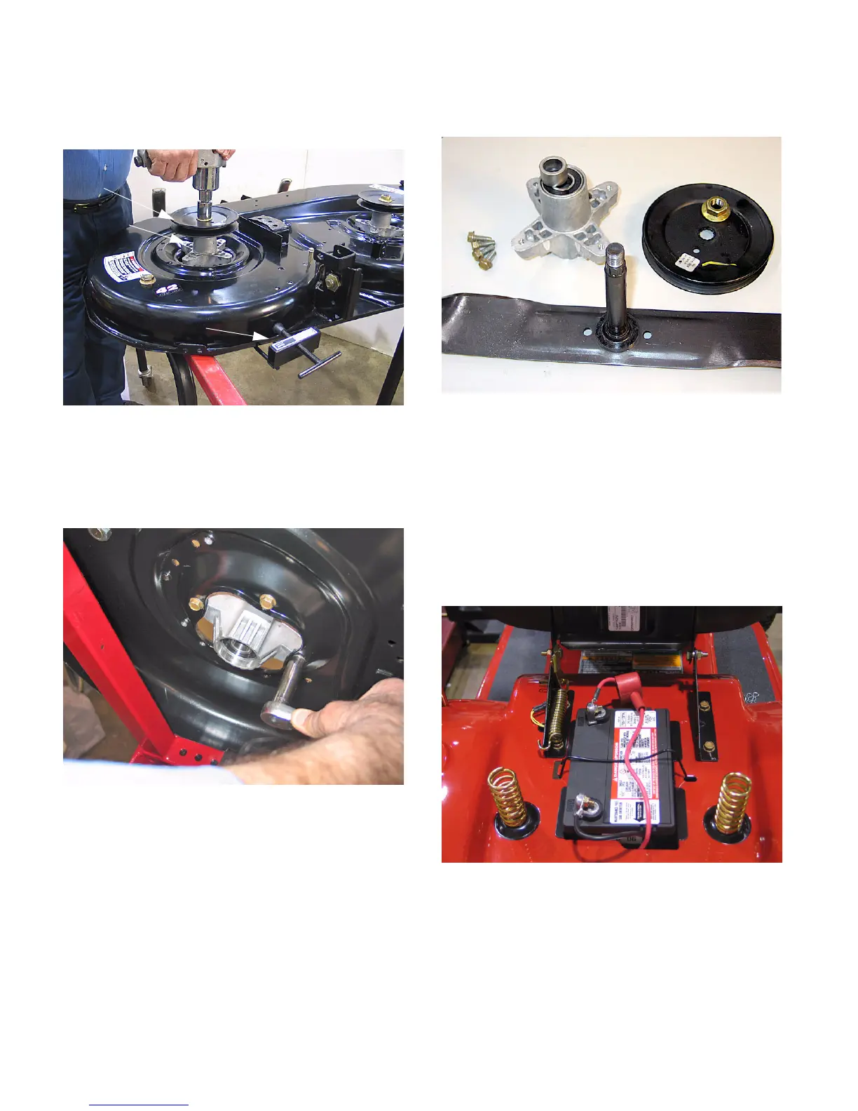
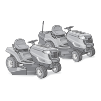
5.5. Using a ½” socket remove the spindle housing
for inspection or replacement. See Figure 16.
5.6. Assemble the spindle in reverse order of disas-
sembly. See Figure 17.
NOTE: During assembly, align the two bearing
spacers inside the spindle as you insert the spin-
dle shaft.
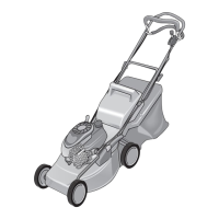
6. FENDER REMOVAL
6.1. Tip the seat forward.
6.2. Remove the battery and battery tray. See Figure
18.
Figure 15
Pulley
Spindle
Blade Stop
Figure 16
Figure 17
Figure 18
www.mymowerparts.com
For Discount White Outdoor Parts Call 606-678-9623 or 606-561-4983