18
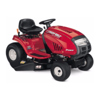
15.9. Using a ½” wrench on the top and a 9/16”
wrench on the bottom, remove the nut securing
the drag link to the steering arm. See Figure 60.
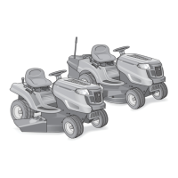
15.10.Remove the sector gear and drag link from the
unit.
15.11. Inspect all components for wear or damage. See
Figure 61.
15.12.Apply lithium grease to the sector gear and
worm gear during assembly.
16. PEDAL SUPPORT BRACKET REMOVAL
16.1. Remove the cutting deck.
16.2. Remove the left side panel.
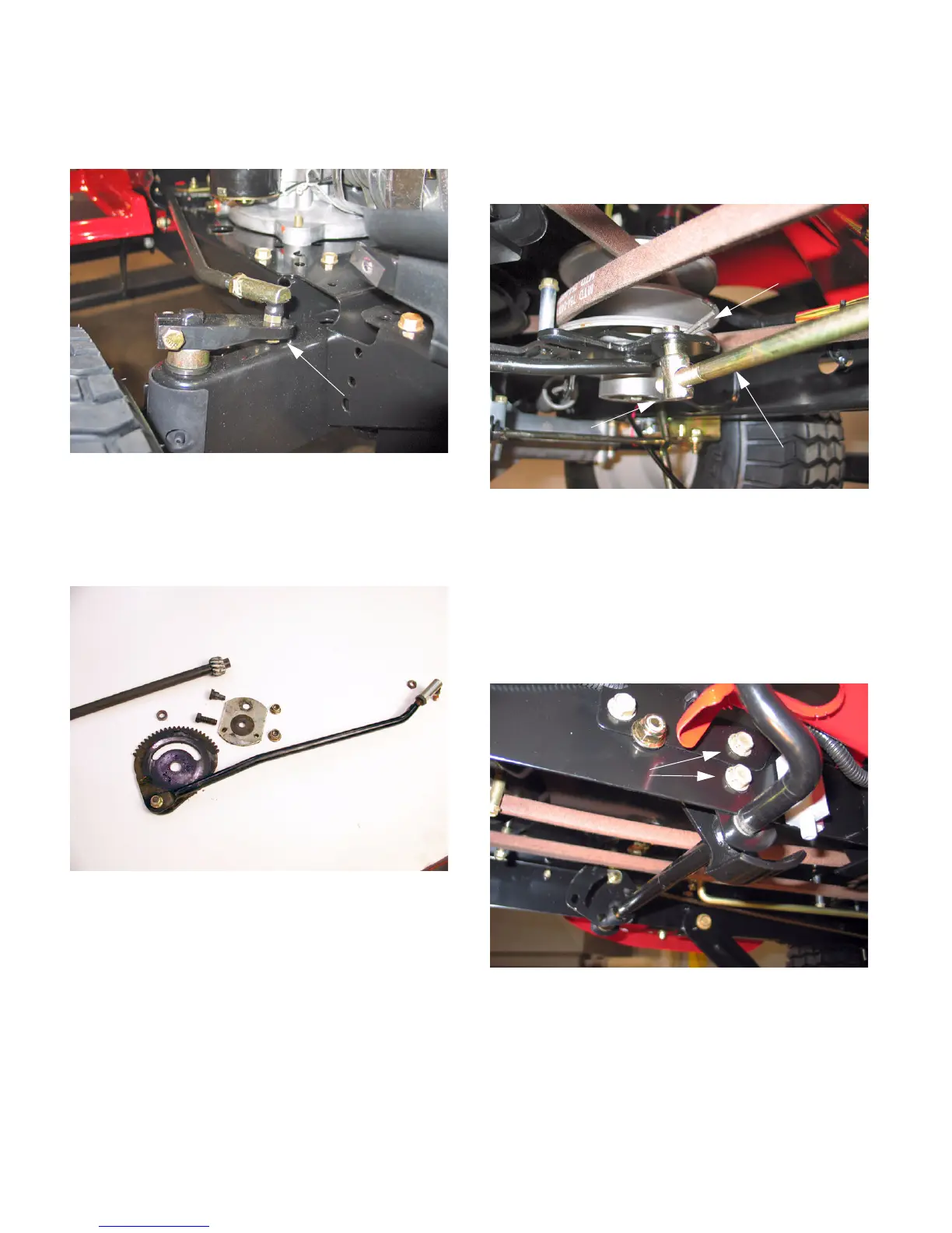
16.3. Working from under the tractor, remove the cot-
ter pin securing the speed control rod to the vari-
able speed idler bracket. Remove the ferrule
from the bracket the let the rod hang down. See
Figure 62.
NOTE: Mark the position of the ferrule on the rod
with some whiteout. This will aid assembly and
allow you to maintain the proper position of the
ferrule.
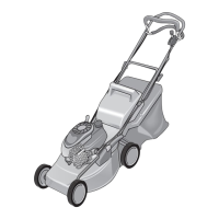
16.4. Using a ½’ socket, remove the hex screws
securing the left side of the pedal support
bracket to the frame. See Figure 63.
16.5. Lower the left side of the bracket from the tractor
as you slide the rod out of the mounting bracket
on the right side of the frame.
16.6. Disconnect the brake rod spring from the brake
arm.
Figure 60
Drag Link Nut
Figure 61
Figure 62
Variable Speed Control Rod
Cotter PIn
Ferrule
Figure 63
Hex Screws
www.mymowerparts.com
For Discount White Outdoor Parts Call 606-678-9623 or 606-561-4983