2
NUMBERING SYSTEM
The LT-5 will follow the same model number configura-
tion as the BFR which was the 600 series (frame size)
but now in the fifth position there will be a ( 7 ) to signify
transition to the new platform.
Example: 13AD789G790
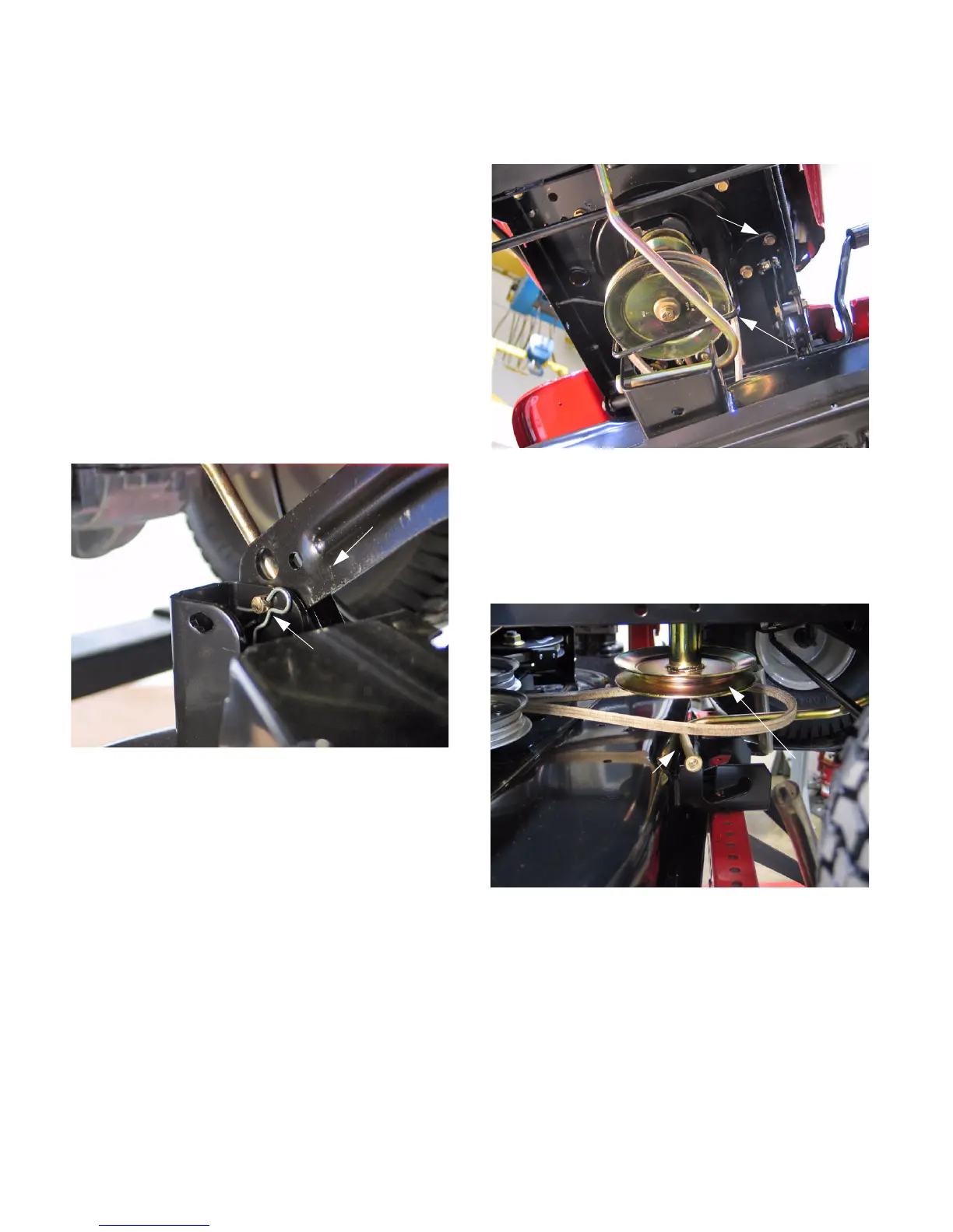
1. DECK REMOVAL
1.1. Place the unit on a firm and level surface.
1.2. Remove the key from the ignition.
1.3. Lower the deck to its lowest cutting position.
1.4. Using needle nose pliers, remove the hairpin
clips securing the deck hanger brackets to the
deck. Release the hanger links from the deck.
See Figure 2.
1.5. Using a 1/2” socket, remove the hex head cap
screw securing the belt keeper to the frame.
Remove the belt keeper. See Figure 3.
NOTE: Note the location of the belt keeper dur-
ing removal. There are two holes in the side
frame. Use the forward hole during assembly.
1.6. Slide the deck forward and remove the deck belt
from around the engine pulley. See Figure 4.
1.7. Lift the front stabilizer from the front stabilizer
bracket.
1.8. Remove front stabilizer adjustment rod by sliding
rod forward untill the flat area is in line with stabi-
lizer bracket notch. Turn the rod 90 degrees and
remove it from the tractor.
1.9. Raise the deck lift lever to its highest cutting
position.
Figure 2
Deck Hanger Bracket
Hairpin Clip
Figure 3
Belt Keeper
Hex Cap Screw
Figure 4
Front Stabilizer
Engine Pulley
www.mymowerparts.com
For Discount White Outdoor Parts Call 606-678-9623 or 606-561-4983