3
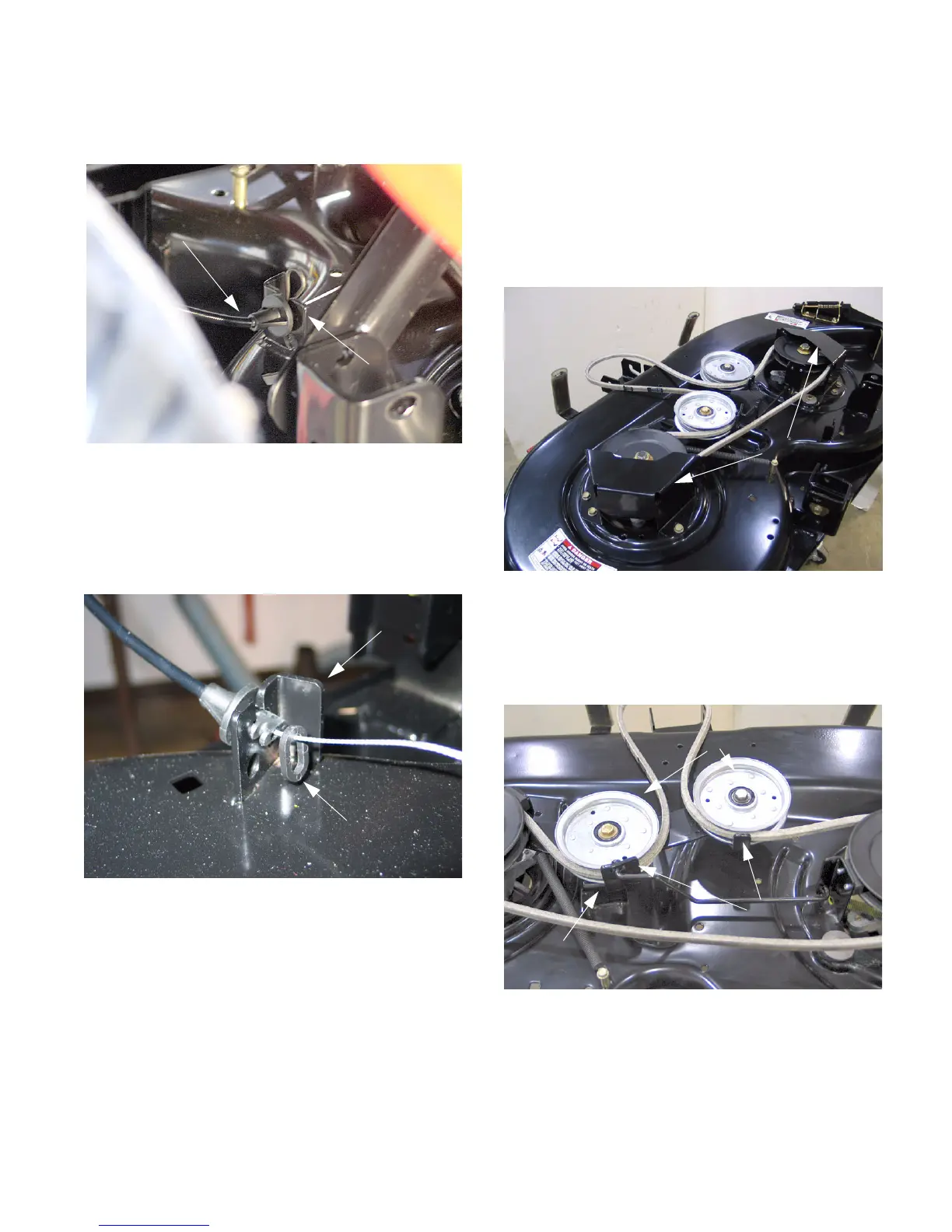
1.10. Using needle nose pliers, remove the hairpin clip
securing the deck engagement cable to the deck
flange. See Figure 5.
1.11. Slip the oval plastic retainer ring from the con-
nector. Pull the connector rearward, lining the
grooves in the connector with the deck flange
and slide it up and out of the flange. See Figure
6.
1.12. Remove the tension spring from the deck idler
bracket.
NOTE: Depending on which deck is installed on
the unit, it may be necessary to remove the spin-
dle brake connecting rod between the two spin-
dles in order to remove the deck engagement
spring.
1.13. Slide the deck out from under the unit.
Figure 5
Deck Engagement Cable
Deck Bracket
Figure 6
Deck Bracket
Oval Retainer
2. BLADE DRIVE BELT REMOVAL
NOTE: The 38” deck has a single pulley on the
idler. The 42” deck has two pulleys on the idler.
Disassembly procedures are similar.
2.1. Remove the cutting deck from the unit.
2.2. Using a ½” socket, remove the three screws
securing the belt cover to the deck. Repeat for
the other belt cover. See Figure 7.
NOTE: The belt covers are interchangeable.
2.3. Using a 9/16” socket and an open-end wrench,
loosen but do not remove the nuts securing both
idler pulleys to the idler bracket. See Figure 8.
2.4. Remove the belt from around the idler pulleys
and spindles.
Figure 7
Belt Covers
Figure 8
Idler Pulleys
Idler Bracket
Belt Guides
www.mymowerparts.com
For Discount White Outdoor Parts Call 606-678-9623 or 606-561-4983