Chapter 3: Air Intake and filter
27
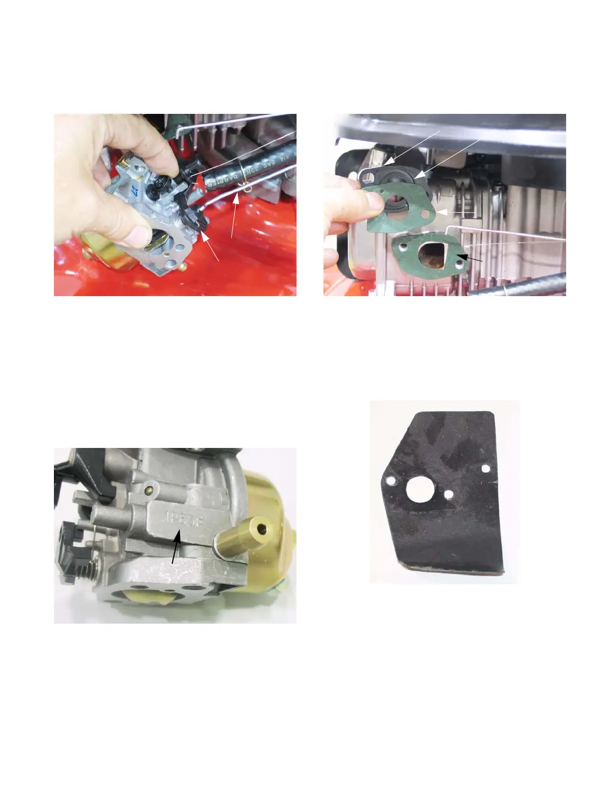
2e. Pivot the carburetor to disengage the Z-fit-
ting on the end of the choke rod.
See Figure 3.14.
2f. Unhook the stabilizer spring that takes-up
the play between the governor arm, the gov-
ernor rod, and the throttle arm on the carbu-
retor.
NOTE: The carburetors are not inter-changeable
from one engine model to another. To help pre-
vent carburetor mix-ups, the engine model num-
ber is stamped on the carburetor by the fuel
nipple. See Figure 3.15.
Figure 3.14
Choke rod
Choke arm
Figure 3.15
Engine model number
3. The insulator is sandwiched between two gas-
kets which are located between the carburetor
and the cylinder head . See Figure 3.16.
NOTE: The gaskets are different, and there is an
orientation to the insulator.
NOTE: On current production the insulator to
cylinder head gasket has been replaced with a
graphite gasket/heat shield. See Figure 3.17.
Figure 3.16
Gasket: insulator
to cylinder head
Gasket: Insulator
to carburetor
Insulator
Bowl vent channel
Figure 3.17
www.mymowerparts.com
For Discount White Outdoor Parts Call 606-678-9623 or 606-561-4983
 Loading...


