Chapter 4: The Fuel System and Governor
45
10. Soak the Carburetor body in a suitable solvent
until clean.
11. Rinse thoroughly.
12. Dry the carburetor body using compressed air.
13. Pre-installation adjustment:
13a. Install the pilot screw gently turning it in all
the way, then back it out 3/4 turn (270
degrees).
13b. Tighten the idle speed screw until 1/8” (3
mm) of the screw is visible on the throttle
arm side of the housing.
14. Reassembly the carburetor and install it by fol-
lowing steps 1-8 in reverse order.
15. Start engine and check the idle RPM using a
tachometer.
NOTE: Idle speed: If applicable, is 1,800 RPM +
160 RPM, set using throttle stop screw.
See Figure 4.50.
• For mower applications, the idle speed is not
normally critical because the operator is not pro-
vided with a throttle control.
Figure 4.50
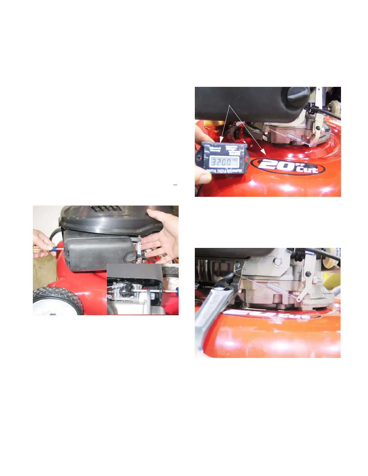
16. Check the top no load speed of the engine.
See Figure 4.51.
NOTE: The top no load speed will vary depend-
ing on the application. The specification for it will
be listed in the manual for each application.
17. Adjust the top no-load speed by slightly bending
the bracket that the governor spring connects to.
The bracket is visible under the air filter.
See Figure 4.52.
Figure 4.51
Digital tachometer confirms safe
operating speed
Figure 4.52
Increase spring tension to
increase engine speed
Decrease spring tension to decrease
engine speed.
www.mymowerparts.com
For Discount White Outdoor Parts Call 606-678-9623 or 606-561-4983
 Loading...


