The ANALOG OUTPUT TEST function is used to test and software trim the 4-20 milliamp analog
outputs and the associated analog output control circuitry.
Press the MODE key to enter the selected test function or press ENTER to continue to the next
test function. Enter the desired analog output (channel) number to test.
The selected analog output number is shown in the right top portion of the LCD (CH#1 in the
example below). The user may press the "1" or the "2" key to set the analog outputs to 4 and 20
milliamps respectively. The "3" and the "4" keys are used to adjust the 20 milliamp trim value. The
current trim value is shown in brackets on line 2 of the LCD, (+2 in the example below). The trim
value can be adjusted from +9 to -9 which will provide a total adjustment range of approximately
0.2 milliamps. Pressing the "5" key will cause the analog output to ramp from 4 to 20 milliamps at
an approximate rate of 12 hertz.
The analog output test is the last available test function. Press the ENTER key to continue to the
SELECT EDIT FUNCTION menu.
1=4ma 2=20ma CH#1
3=ADJ+ 4=ADJ- [+2]
5=RAMP OUTPUT
‘Enter’ TO CONTINUE
SELECT ANALOG OUTPUT
TO TEST: (1-8)
‘Enter’ TO CONTINUE
ANALOG OUTPUT TEST
‘Mode’ TO TEST
‘Enter’ TO CONTINUE
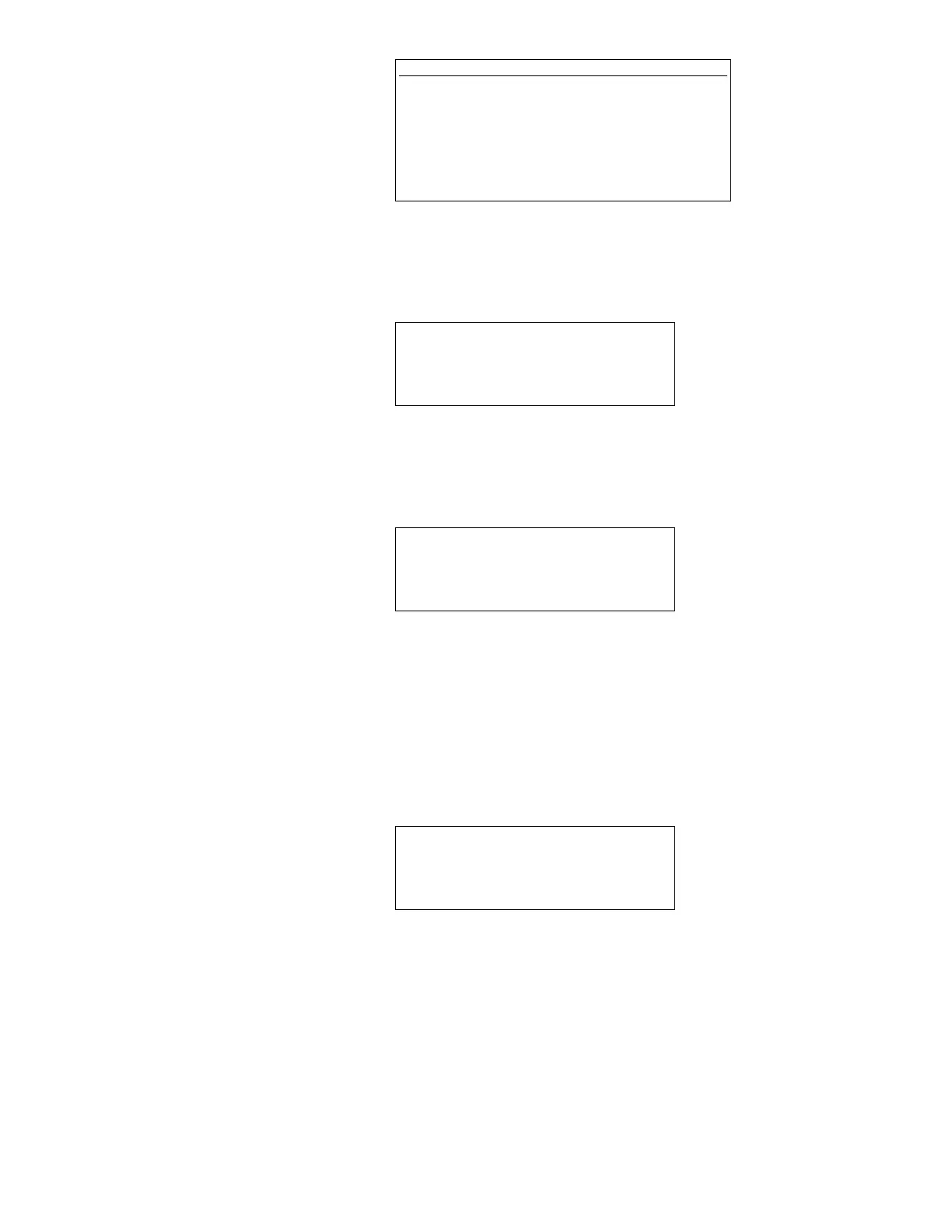
NOTE
External communication equipment (EIA485 or
EIA232 compatible depending on Level Plus monitor
host port configuration) will be required to input
characters into the host communication port to verify
the receive functionality. The baud rate/word length
parameters for the host communication port are
defined in the previous section.
72