7.6.2 Injector – Removal and installation
Preconditions
☑ Engine is stopped and starting disabled.
Special tools, Material, Spare parts
Designation / Use Part No. Qty.
Socket wrench
F30452389 1
Screwdriver bit T45
F30454548 1
Puller
F6790992 1
Assembly sleeve
F30454554 1
Injector alignment device
F6795554 1
Alignment mandrel
F6795777 1
HP line alignment device
F6795725 1
Torque wrench, 20–100 Nm
F30026582 1
Assembly compound (Kluthe Hakuform 30-15)
X00067620 1
Engine oil
Sealing ring
(→ Spare Parts Catalog)
O-ring
(→ Spare Parts Catalog)
O-ring
(→ Spare Parts Catalog)
WARNING
Fuels are combustible and explosive.
Risk of fire and explosion!
• Avoid open flames, electrical sparks and ignition sources.
• Do not smoke.
• Wear protective clothing, protective gloves, and safety glasses / facial protection.
Preparatory steps
1. Close off fuel supply to engine.
2. Remove cylinder head cover upper section (→ Page 83).
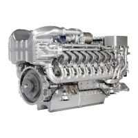
Injector – Removal
1. Remove HP line (1) using socket wrench.
2. Disconnect cable at control cable connec-
tion (7) of injector (3).
3. Remove cylinder head cover lower sec-
tion (2).
4. Release both screws (6) on flange.
5. Remove retaining screw (4) from hold-down
clamp (5) with screwdriver bit.
MS150119/01E 2016-02 | Injector | 89
TIM-ID: 0000055245 - 006