Manual
41
12.8.4. Activating the Elevator-Tr (Ele -Tr) input
in the FLAP+ mixer (snap-flap)
The term Snap-Flap is used when elevator is mixed
into the camber-changing flaps or ailerons. This func-
tion is prepared in the mixer AILERON+ and FLAP+.
Input 4 for both mixers is Ele -Tr.
The suffix “-Tr” means “without trim”. If you adjust the
elevator trim at the transmitter, the aileron and flap
settings are unaffected by the change.
!
Note: Snap-Flap and switches
If Snap-Flap is switched on at excessive airspeeds,
very high aerodynamic forces can occur which may
damage or even wreck the model. Please: take care
when using this function!
The procedure for setting up Snap-Flap:
a. Checking / changing the switch
The Ele -Tr input is switched using the mixer
switch Mix-1 (logical switch). Switch G with the
ON position “back” (G#) can be prepared as the
physical switch in assignment list 2 GLIDER.
- Main menu: ¡Setup
- Menu: Assignment, Switches
Mix-1 G> #*
In this menu you can also change the switch or
the switch position for Snap-Flap “ON”:
- Open the menu point with ENTER
- Confirm the warning message with ENTER
- Operate the desired switch repeatedly
- Move the switch to the position for ON
- Close the menu point again with ENTER.
!
If you are using a three-position switch, only the
two end-points can be set as the ON position.
b. Setting the control surface travels
- Main menu: £Mixer
- Menu: AILERON+
- Menu point: Ele -Tr
- Open the menu point with ENTER
- Move switch G to the ON position
(* must be displayed)
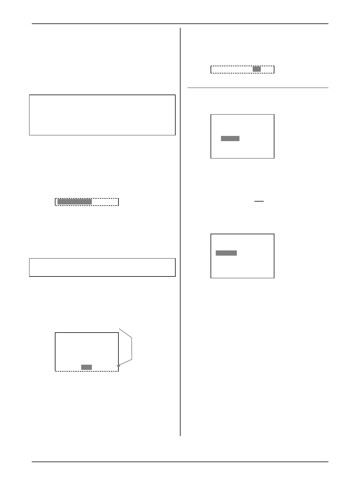
£Mixer.AILERON+
¨Exit
š trv' trv#
Aileron –---- 100% *
Spoiler – OFF -65% *
Flap – 18% 18% *
Ele -Tr– 15% OFF G*
Set a test value of 15% control surface travel, then
check with the elevator stick (back-stick) that the
ailerons move down.
If so: hold the elevator stick in that position, and
set the desired travel.
If not: press the REV/CLR button to change the
value to -15%. Now hold the stick in position and
set the desired travel.
Press ENTER to switch to the second parameter,
and repeat the procedure with “down-elevator”,
and the up-travel of the ailerons.
Note: The prefixes for the first and second pa-
rameters must be the same!
Ele –Tr – 15% 18%G*
12.9. V-tail models
12.9.1. Assigning V-tail servos
In the Servo Assignment menu you must change the
tail servos ELEVATR+ and Rudder to V-TAIL+:
¤Servo.Assign
¨Exit
1 AILERON+ UNI 3P
2 V-TAIL+ UNI 3P
3 V-TAIL+ UNI 3P
4 Throttle UNI 3P
5 AILERON+ UNI 3P
ª6 FLAP+ UNI 3P
The compensating inputs for Spoiler, Flap and
Throttle can also be mixed into the V-TAIL+ mixer.
12.9.2. Activating the mixer V-TAIL+
!
When you assign the V-tail servos, you will find
that the V-tail still does not respond to any control
commands, as the default value for all the mixer in-
puts is OFF.
For this reason you should first set both travel inputs
for Elevator to, say, 60% in the V-TAIL+ mixer:
£5x Mixer.V-TAIL+
¨Exit
š trv' trv#
Elevator– 60% 60% *
Rudder – OFF OFF *
Spoiler – OFF OFF *
Flap – OFF OFF *
Thr -Tr – OFF OFF *
12.9.3. Checking / changing the direction of
servo rotation
With the travel settings you have just entered, the V-
tail servos will now respond to the elevator stick.
Apply up-elevator (back-stick) and watch the V-tail. If
either or both servos rotate in the wrong direction, re-
verse them at this point.
- Main menu: Open ¤Servo
- Menu: Select and open Calibrate
- Line: Select á
- Press ENTER to select Parameter
- Press REV/CLR to reverse the servo direction
- Move the elevator stick to check the direction of
rotation
- If all is well, press ENTER to end the procedure.
If necessary, you can now reverse the second servo
or adjust the other inputs.