WTB-16PD TRACK-DRIVE POWER BUGGY • OPERATION MANUAL — REV. #0 (08/31/20) — PAGE 39
PRESSURE TESTING
To ensure optimal performance of your track buggy,
hydraulic pressure checks should be performed periodically.
The following hydraulic pressure checks should be checked:
Dump/Pivot Valve Pressure
Charge Pressure (Return)
Left-Side Hydraulic Motor (Forward/Reverse)
Right-Side Hydraulic Motor (Forward/Reverse)
Multiquip offers a ‘Special Test Pressure Gauge Kit.’ When
installed, the disconnection of hydraulic hoses is no longer
required.
Simply unscrew the protective cap and insert the pressure
gauge into the test port. Installation of the test pressure kit
makes pressure testing quick and easy.
Charge Pressure (Return)
1. To gain access to the hydraulic oil filter, place the tub
in the dump (vertical) position.
2. Lift up on the access panel to gain entry to the pump
and hydraulic compartment area. Secure the access
panel with the latch.
3. Remove the hydraulic hose connected to the 90° fitting
from port A on the dump/pivot valve (Figure 44A).
4. Insert the T-fitting and gauge into the 90° fitting.
5. Start the engine. Prior to testing, warm the hydraulic
system oil until it reaches 100°F.
6. Increase engine RPMs to high speed. The test gauge
should read 215–216 psi (14–15 bar).
Hydraulic Drive Motors
1. Place the parking knob in the ON position (brake set).
2. Locate the left and right track hydraulic drive motors
at the bottom front of the machine.
3. Remove the hydraulic hose connected to the 90° fitting
(Figure 44B) from port A (top) on the hydraulic pump
(pump 1). This port is for the left-side hydraulic drive
motor reverse direction. Refer to the hydraulic diagram.
4. Insert the test gauge into the 90° fitting (top).
5. Start the engine and run at high speed. Momentarily
push the travel lever to full travel for a few seconds, just
long enough to read the test gauge. The value should
read 4,350 psi (300 bar).
MAINTENANCE
6. Stop the engine.
7. Reconnect the hydraulic hose back onto the 90° fitting,
port A (top).
8. Remove the hydraulic hose connected to the 90° fitting
(Figure 44B) from port B (bottom) on the hydraulic
pump. This port is for the left-side hydraulic drive motor
forward direction.
9. Insert the test gauge into the 90° fitting port B (bottom).
10. Start the engine and run at high speed. The test gauge
should read 4,350 psi (300 bar).
11. Stop the engine.
12. Reconnect the hydraulic hose back onto the 90° fitting,
port B (bottom).
13. Repeat this procedure for the right-side hydraulic drive
motor (hydraulic pump 2).
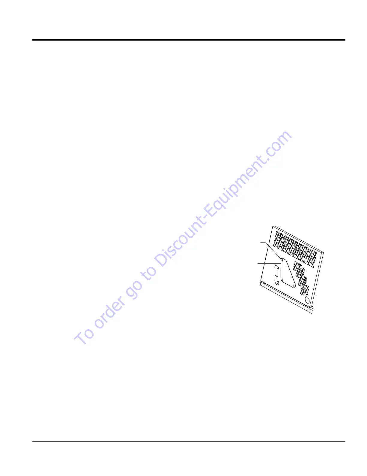
Dump Valve Pressure
1. To gain access to the dump/pivot valve, remove the
three screws that secure the access cover to the panel.
Figure 43. Access Cover
2. Remove the hydraulic hose connected to the 90° fitting
from port A on the dump/pivot valve (Figure 44C).
3. Insert the T-fitting and gauge into the 90° fitting.
4. Start the engine and place the dump lever in the dump
position. The tub should be in the vertical position. The
test gauge should read 1,800 - 1900 psi (124 - 131 bar).
5. Stop the engine and reconnect the hydraulic hose back
onto the 90° fitting, port A.
DUMP VALVE
ACCESS
COVER
RETAINING
SCREWS (3)
REMOVE
To order go to Discount-Equipment.com