3–3
5. Do not locate the intake and outlet for the process air too close together. If possible,
allow a distance of at least 5 feet. Allow the same distance between the inlet and
outlet for the reactivation air.
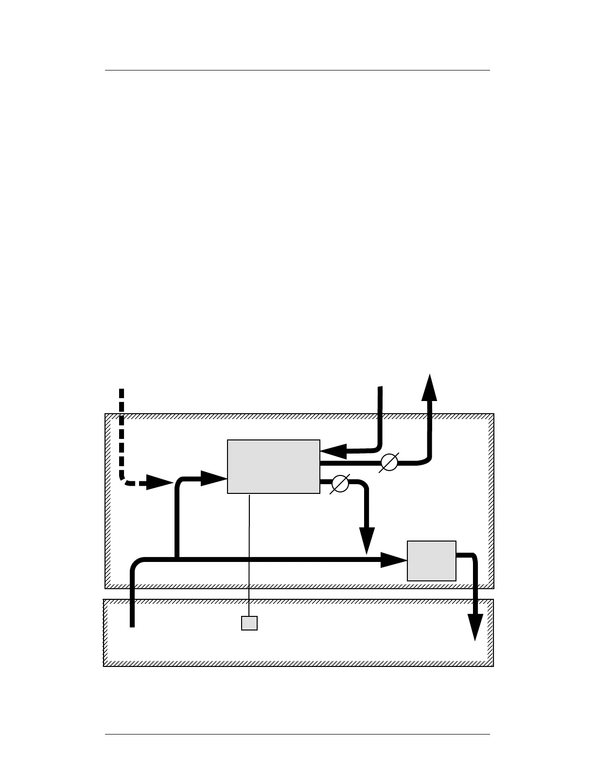
6. Figure 3–3 shows the set-up if you are installing the HC-150 in a system with an
existing air-handling unit. Notice that both sides of the HC-150 are connected
upstream of the air-handling unit.
Do not connect the HC-150 so that it bypasses the air-handling unit. See Part A of
Fig. 3–4. If you connect the ductwork this way, some of the air from the air-handling
unit may be forced back through the HC-150, and the HC-150 will not be able to
work correctly.
You may connect both sides of the HC-150 downstream of the air-handling unit, as
shown in Part B of Fig. 3–4. The arrangement shown in Fig. 3–3 is better, however.
This set-up allows the air-handling unit to heat or cool the processed air after it
leaves the HC-150.
7. On some installations, “makeup” air is taken from outside the process space, and
added to the process air stream. Unconditioned makeup air can add a moisture
FIGURE 3–3
HC-150 INSTALLED WITH EXISTING AIR-HANDLING UNIT
Reactivation air IN –
from outdoors
Reactivation air OUT –
to outdoors
Process air
IN
Process air
OUT
Optional makeup air IN –
from outdoors
HUMIDISTAT
(option)
OUTDOORS
PROCESS SPACE (STORAGE AREA)
J138
Damper
Damper
HC-150
DEHUMIDIFIER
Return air IN –
from process space
PROTECTED SPACE
PROTECTED SPACE
AIR
HANDLING
UNIT
 Loading...