3–2
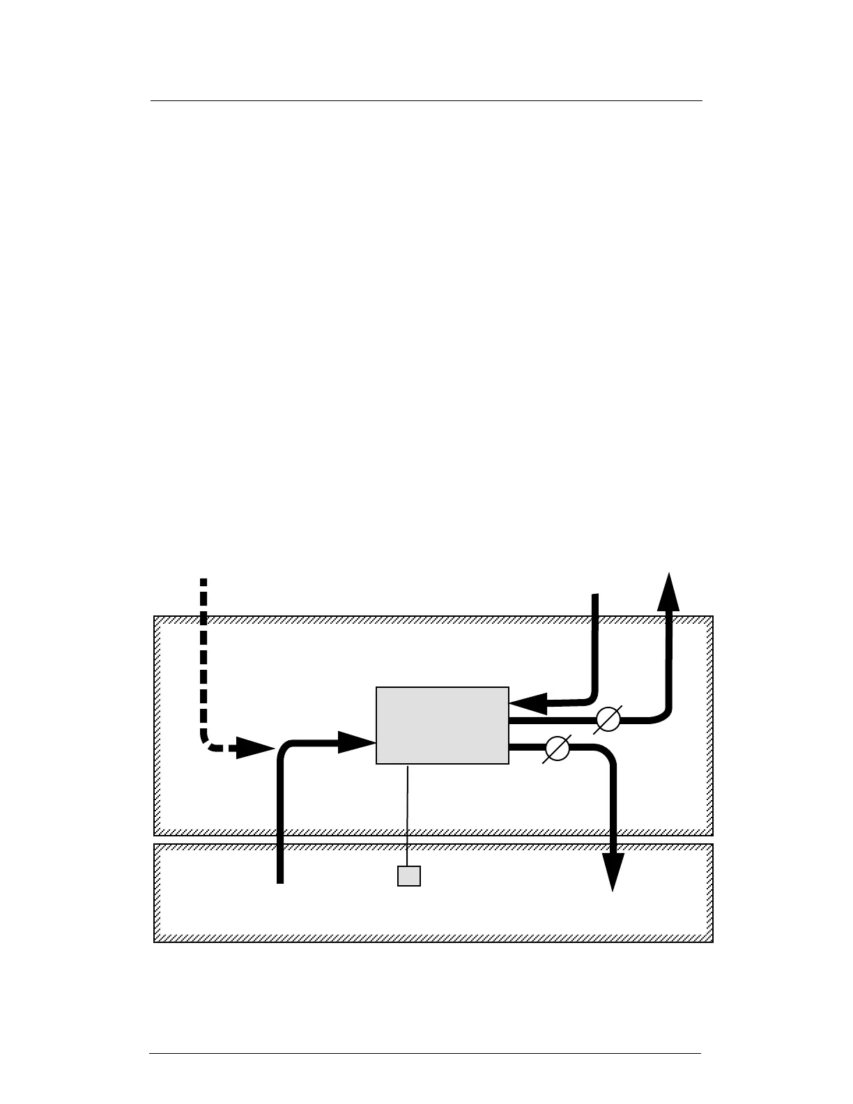
FIGURE 3–2
HC-150 INSTALLED OUTSIDE OF PROCESS SPACE
•a 7" space in front of the reactivation air intake to allow smooth air flow (not
necessary if ductwork is installed)
2. Figures 3–1, 3–2 and 3–3 show three different ways of installing the HC-150.
3. There are some simple rules for arranging the ductwork for the HC-150:
Process air intake .............. Taken from the storage space
Process air outlet ............... Vented to the storage space
Reactivation air inlet ........... Taken from a separate space (not from storage space–
don’t use dehumidified air)
Reactivation air outlet ........ Vented outdoors (air is very damp–don’t use for space
heating)
(Note – The reactivation air can also be taken from and returned to an indoor space
where the temperature and humidity levels are not important.)
4. Wherever the intake or outlet ducts open outdoors, protect them from the elements.
Install weather hoods and bird screens.
Reactivation air IN –
from outdoors
Reactivation air OUT –
to outdoors
Process air IN –
from process space
Process air OUT –
to process space
Optional makeup air IN –
from outdoors
HUMIDISTAT
(option)
OUTDOORS
PROTECTED SPACE
J137
PROTECTED SPACE
PROCESS SPACE
(STORAGE AREA)
Damper
Damper
HC-150
DEHUMIDIFIER