2202L5JE-DA-C5-N_2015.05.
5 Maintenance and Inspection
Compound 2-stage Screw Compressor 5.5 Reassembly
1612LSC Speed Increaser Type
5-60
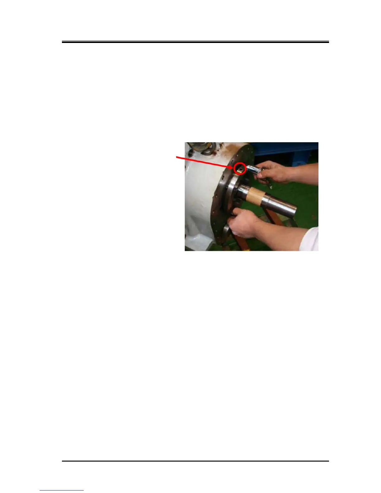
f)
Install the thrust bearing gland [190] by finger-tightening the hexagon head bolts [191] evenly with
the gland’s oil return hole (for speed increaser gear side bearing lubrication) facing up as shown in
the picture below).
Finally tighten these bolts after installing the speed increaser gear casing assembly to the bearing
head of the low-stage compressor section, that is, after the roller bearing’s inner race on the speed
increaser gear spindle has properly engaged with the roller bearing’s outer race on the bearing
head (namely the spindle is finally positioned).
Oil Return Hole
 Loading...


