2200LZJE-HO-C6-N_2013.12.
Chapter 5 Maintenance
Compound 2-stage Screw Compressor 2016**C 5.6 Overhaul
5-20
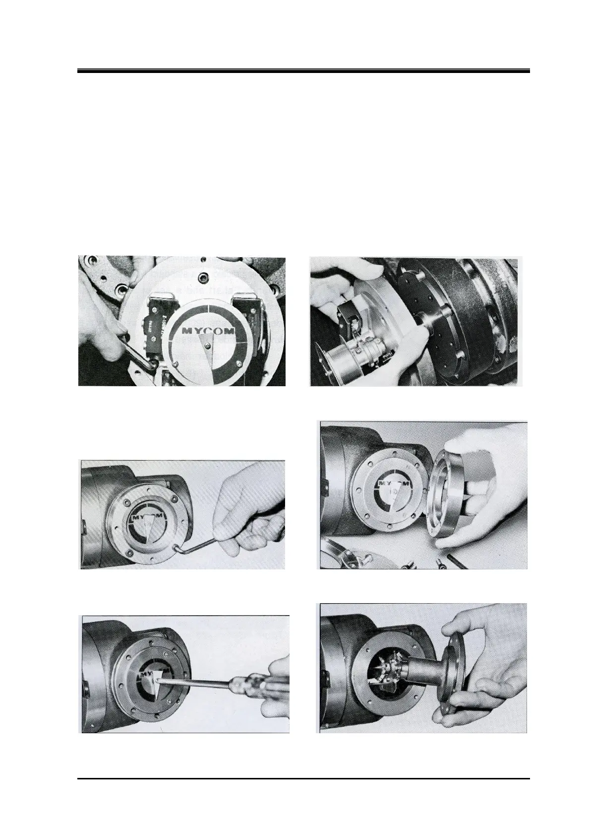
When further disassembly is necessary
The indicator is an assembly. Unless it needs to be disassembled, remove it as a unit and do not
disassemble it into smaller parts.
○ High-stage/Low-stage
a) As a result of the disassembly process conducted above, (i) the internal potentiometer, (ii)
micro-switch and (iii) micro-switch base plate 【 121 】 attached with micro-switch cam get
removable.
b) Remove hexagon socket head cap screws 【122】.
c) Loosen the micro-switch cam set screw 【128】.
d) Now, the assembly can be pulled out as it is if pulled out in the axial direction.
Photo 015 Loosening the Screws Photo 016 Removing High-stage Indicator
Securing High-stage Micro-switch Base Plate
Photo 017 Removing Low-stage Indicator Photo 018 Removing Low-stage
Indicator Cover
Photo 019 Removing Low-stage Indicator Pointer Photo 020 Low-stage Indicator Inside