2201Q4JE-MY-C9-N_2018.01.
Chapter 5 Maintenance and Inspection
Compound 2-stage Screw Compressor 4032**C 5.4 Disassembly and Inspection
5-18
5.4.3 Unloader Piston and Unloader Cylinder
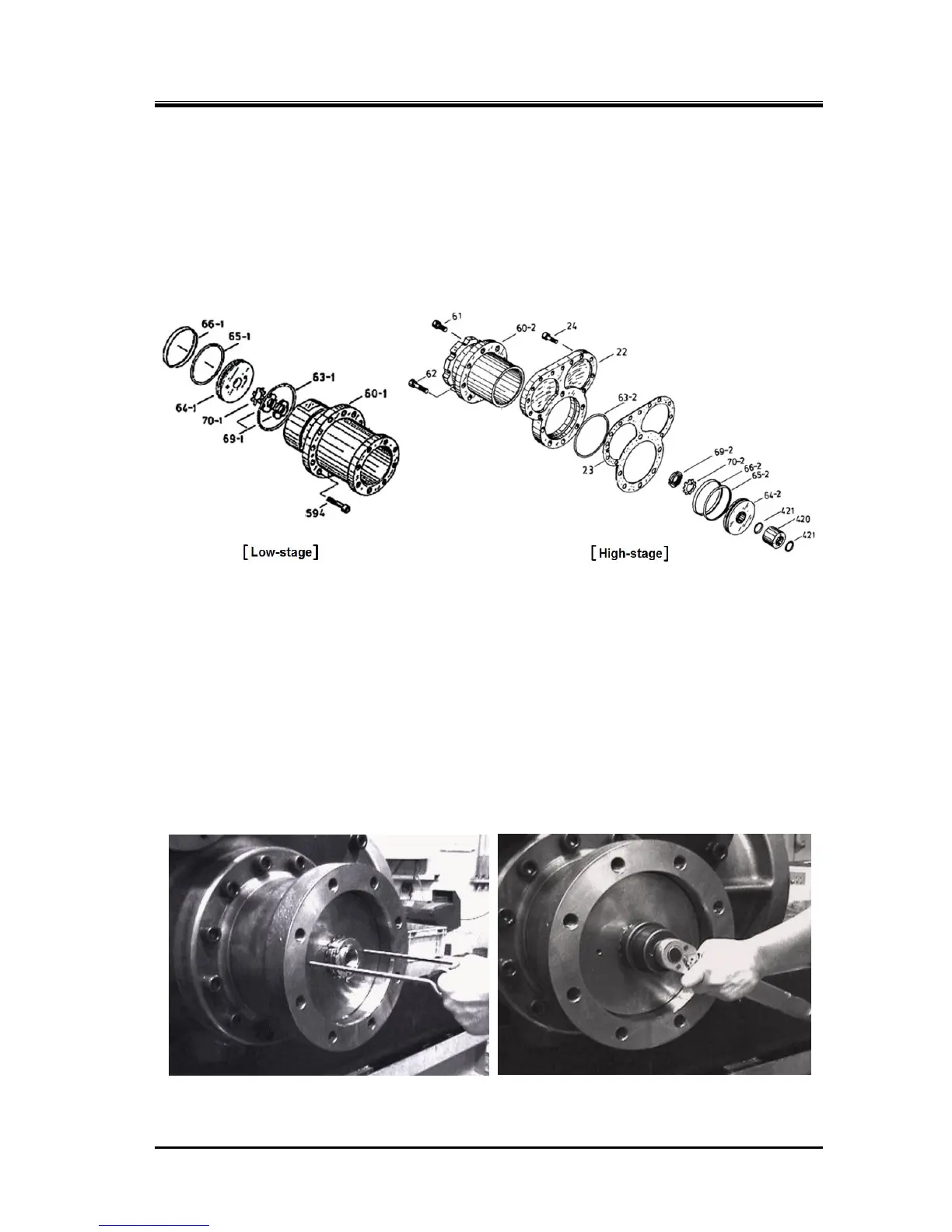
Inside the unloader cylinder [60-1] [60-2] is an unloader piston [64-1] [64-2] around which the cap seal
[66-1] [66-2] and O-ring [65-1] [65-2] are fitted. The unloader piston is assembled to the unloader push
rod [67-1] [67-2], which operates the unloader slide valve, with the lock nut [69-1] [69-2].
Note that the low-stage lock nut [69-1] has a double nut arrangement, and that in the high-stage
unloader cylinder 30 % (indicated load) unloader spacer is installed to prevent an abnormally high
intermediate pressure at the time of compressor start-up.
Figure 5-6 Unloader Cylinder Block
5.4.3.1 Disassembly
a) Screw two M8 eyebolts in the thread holes of the unloader piston, and pull the unloader piston
[64-1] [64-2] fully towards you.
b) Since the low-stage lock nut [69-1] fixing the unloader piston on the unloader push rod has a
double nut arrangement, loosen and remove the front side nut by using a lock nut wrench.
c) Then, release the locking teeth of the lock washer [70-1] [70-2], such that the lock nut [69-1] [69-2]
can be turned. Then, loosen the lock nut using a lock nut wrench, and remove it.
d) Pull out the unloader piston using the M8 eye bolts again.

 Loading...

