2201Q4JE-MY-C9-N_2018.01.
Chapter 2 Compressor Specifications and Structure
Compound 2-stage Screw Compressor 4032**C 2.5 Mechanisms
2-10
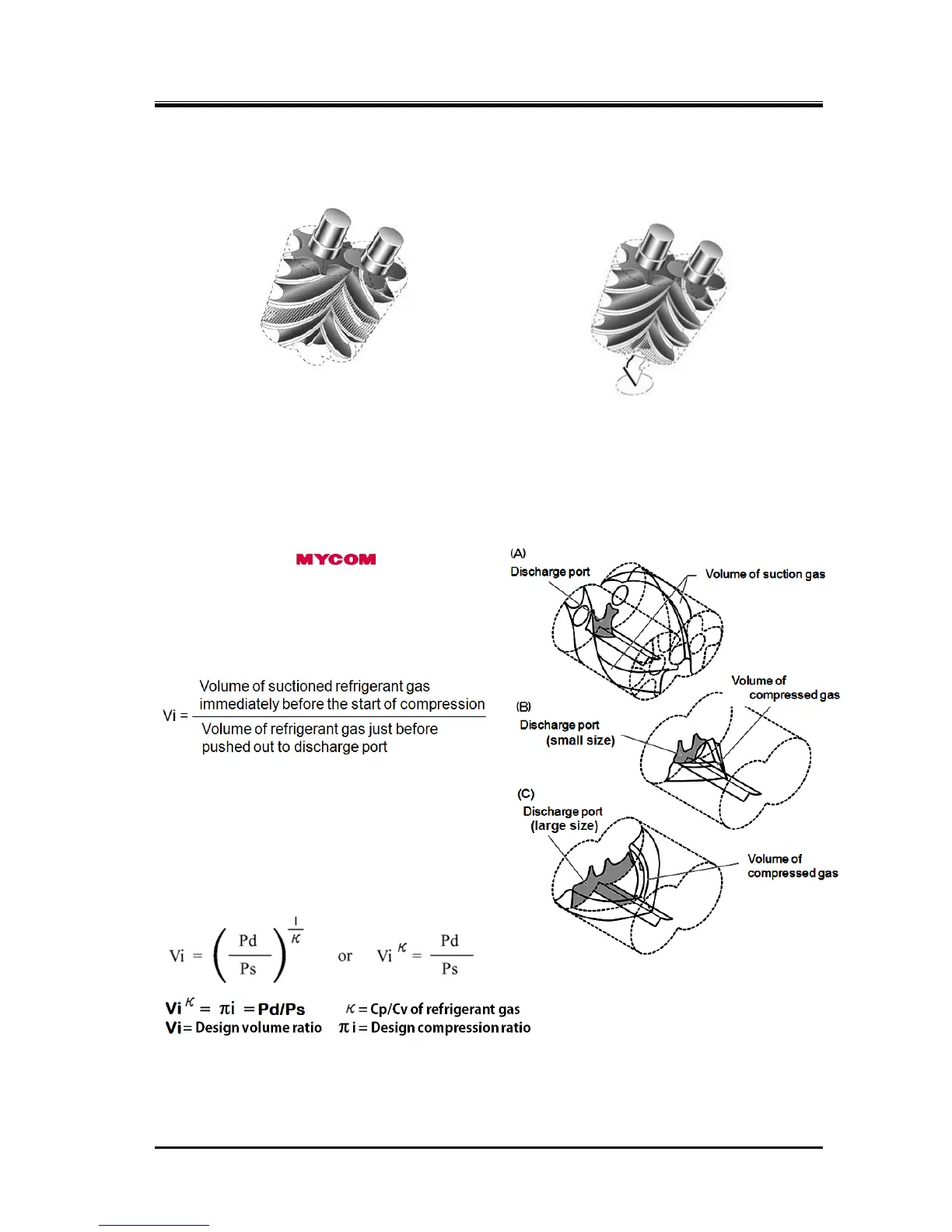
2.5.3 Compression Process
As the rotors rotate further, the volume between the rotor lobes decreases while the sealing line moves
toward the discharge side, which compresses the trapped refrigerant gas.
2.5.4 Discharge Process
The volume between the rotor lobes decreases to a level predetermined by the discharge port. With the
rotations of the rotors, the compressed refrigerant gas is pushed out to the discharge port.
2.5.5 About Volume Ratio (Vi)
Volume ratios (Vi) of C-series screw
compressors are indicated in performance tables or
catalogs by using port symbols L and M.
The volume ratio represented by each symbol is
as follows:
L=2.63, M=3.65
Which volume ratio (L or M) should be used is
decided according to operating conditions. If the
compressor is used with a volume ratio that does
not match operating conditions, operation will go
inefficiently wasting the power.
The relationship between volume ratios and
generally used compression ratios is as follows:
As Vi is affected by the constant of the refrigerant gas, its value that corresponds to the compression
ratio will change depending on the refrigerant gas.

 Loading...

