2201Q4JE-MY-C9-N_2018.01.
Chapter 5 Maintenance and Inspection
Compound 2-stage Screw Compressor 4032**C 5.5 Reassembly
5-41
5.5.6 Installing the Suction Cover
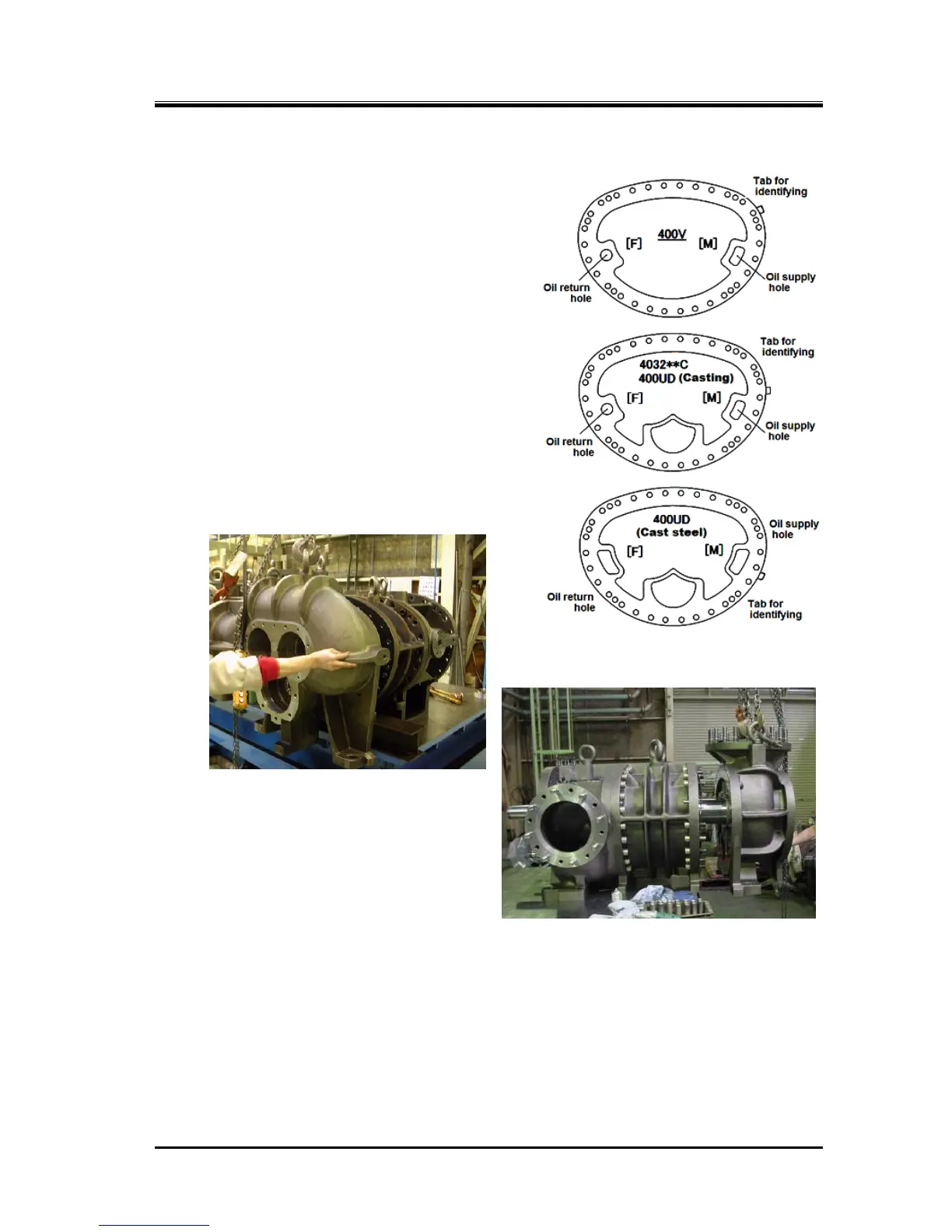
Both of the high-stage and low-stage suction cover
gaskets [6] are not symmetrically shaped.
Also, as shown in Figure 5-19, there are three type
gaskets in the same sizing. Be careful not to use a wrong
gasket.
After the design modification in June 2008, the tabs have
been added on the suction cover gasket for identifying
the left/right and the applicable model
a) Apply sufficient oil on both sides of the gasket,
confirm the oil supply/return holes position and put
the gasket on the main rotor casing.
b) At first on the high-stage, pass the unloader push rod
through the hole at the bottom of the suction cover
[5-2].
Slide (or use a lifting device to move) the suction
cover in parallel along the shaft axis to engage the
rotor shafts with the side bearings. At this time, be
careful not to damage the inside surface of the side
bearing by the shaft end.
As the low-stage unloader push rod is out to
the bearing head side, be careful only with the
rotor shaft end in this work.
c) After the suction cover has been pushed in up
to the flange surface, lightly fasten some of the
bolts [2].
d) Using a copper hammer or an aluminum
hammer, drive in the alignment pins [3].
e) Tighten the hexagon socket head cap screws
evenly up to the specified tightening torque.
The bolts on the bottom side (about 6 bolts) are to be tightened during the final assembly stage, on
the special stand used in the disassembly process.
f) For both the high-stage and low-stage blocks, move the unloader push rod back and force by hand
to check that it is working normally.
g) Hold and rotate the M rotor shaft to check if it works normally.
In addition, check that the rotor has an axial play (i.e., the rotor can move in the axial direction).

 Loading...

