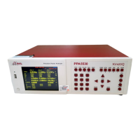
PPA55xx Quick User Guide
Page 26
The information given in this section cannot be
changed by the user
Instruments unique serial number
Code attributed to build date of instrument
Current firmware release installed in instrument
Digital Signal Processing release version
Field Programmable Gate Array release version
Release version of Instruments boot up firmware
Instruments last calibration date
Manually enter company name
Manually enter individual or company
Manually enter unique ID for instrument
The RMS voltmeter displays the additional secondary
parameters of ac, crest factor, surge, mean and form
factor
The phase meter mode is a secondary function which
does not have a separate button. The phase meter
uses the terminology of channel 1 for voltage and
channel 2 for current as it is normal to use a phase
meter to compare voltages directly. The phase meter
measures the phase and gain of channel 2 relative to
channel 1 using a Discrete Fourier Transform (DFT)
algorithm at the fundamental frequency
In the POWER mode, the analyzer measures power
values for each phase
The IMP mode on the PPA uses the real and imaginary
components at the fundamental frequency using DFT
analysis to compute the impedance of the load and
associated parameters
In the INTEG mode, the PPA will compute additional
power values within a Datalog and display them
relative to time (total power)
The HARM mode of the PPA computes multiple DFTs
on the input waveforms in real time. There are two
modes of operation: difference THD, and series
harmonics. Series harmonic mode includes options for
THD, TIF, THF, TRD, TDD and phase. There is also an
option of a series harmonic bargraph display which
shows both the voltage and current harmonics
simultaneously. In difference THD mode, the THD
(Total Harmonic Distortion) is computed from the rms
and fundamental: In series THD mode, the THD is
computed from a series of up to 125 harmonics

 Loading...