16
AMPLIFIER ADJUSTMENT
Idle Current
1. Rotate R5221 fully clockwise.
2. Connect DC millivoltmeter to P5501 (i.e. Across half of R5228 and R5530, 0.22 Ohm resistor).
3. Turn on the unit.
4. Adjust R5221 for 2mV +/- 0.2mV reading on voltmeter.
5. Leave power on for at least 5 min, and check for idle current again.
6. Repeat for other channels.
CHANNEL JUMPER VR
FL P5501 R5521
FR P5001 R5021
C P5101 R5121
SL P5601 R5621
SR P5201 R5221
BS P5701 R5721
BSR P5301 R5321
ISC Adjustment
A. Rotate R8214 fully clockwise.
B. Use 500mV, 1kHZ sine wave, EXT7.1 input, 8ohm loading to all channels.
C. Increase the output power of FL/SL/BSL channels to 80W(25.3V).
D. Note the THD readings should be larger than 0.2%.
E. Rotate R8214 anti-clockwise slowly until the THDreadings is below 0.1%.
F. Repeat for R8217 using FR/SR/BSR/C channels.
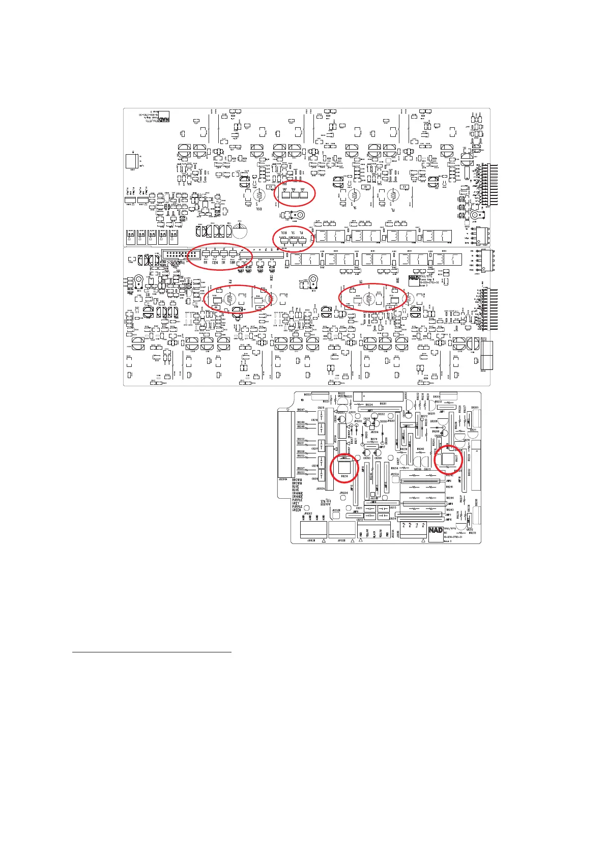
ADJUSTMENT POINT DIAGRAM
LEFT/RIGHT CHANNEL AMPLIFIER BOARD
SECONDARY / ISC BOARD