Do you have a question about the NAD T 761 and is the answer not in the manual?
Precautions to prevent fire and shock hazards during servicing.
Recommendations for safe and effective product installation.
Essential safety guidelines to follow before and during servicing.
Step-by-step procedure for checking insulation resistance.
Precautions for handling sensitive electronic components to prevent damage.
Guidelines and part numbers for replacing fuses safely.
Final safety checks before returning the product to the customer.
Specifications for power output, distortion, sensitivity, and S/N ratio.
Specifications for surround channel separation and frequency response.
Technical specifications for the AM tuner performance.
Technical specifications for the FM tuner performance.
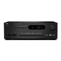
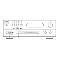
Labeled diagram and description of rear panel connections and features.
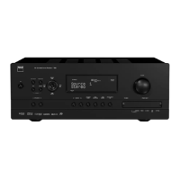
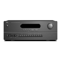
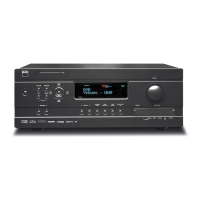
Labeled diagram and description of front panel controls and indicators.
Illustration showing screw locations for panel removal.
Illustration showing top cover removal procedure.
Key to understanding wiring diagram symbols.
Functional block diagram illustrating signal flow and main components.
Diagrams indicating adjustment points on Tuner and Amplifier boards.
Required test equipment setup for measurements and adjustments.
Step-by-step procedures for aligning the amplifier section's idle current.
Alignment steps for FM mono, stereo, distortion, separation, and RDS.
Alignment steps for AM modulation and tuning.
Component layout for Speaker, Primary, and Secondary PCBs.
Component layout for Digital In, Digital Out, and S-Video Boards.
Component layout for PSU and Component Video Boards.
Component layout for Video 5, Load, and Volume Boards.
Component layout for Surround Amp and AC3 Boards.
Component layout for the AC3 Board (Solder Side).
Component layout for the Front Amp Board.
| Power Output | 100 watts per channel (8 ohms) |
|---|---|
| Total Harmonic Distortion | < 0.05% |
| Input Sensitivity | 200 mV |
| Signal-to-Noise Ratio | > 100 dB |
| Dimensions | 17.1 x 14.2 x 6.3 inches |
| Weight | 24.2 lbs |
| Input Impedance | 47 kOhms |
| Tuner Bands | AM/FM |
| Surround System Class | Dolby Digital, DTS |
| Digital Sound Processor (DSP) | Yes |
| Bass Control | Yes |
| Treble Control | Yes |
| HDMI Switching | No |
| Damping Factor | > 100 |
| Speaker Impedance | 4-8 ohms |
| Frequency Response | 20 Hz - 20 kHz |
| DSP Presets | Multiple presets |