Do you have a question about the NAD T 752 and is the answer not in the manual?
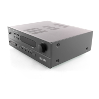
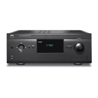
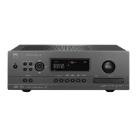
Model name and description of the audio receiver.
Important safety warnings regarding electrical shock and proper handling.
Guidance on replacing fuses with the correct type to prevent fire hazards.
Procedures for ensuring product safety before customer return, including measurements.
Technical specifications for the power amplifier stage.
Technical specifications related to Dolby Digital audio processing.
Technical specifications for Dolby Pro Logic II audio processing.
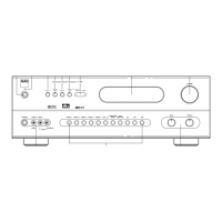
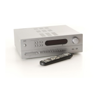
Identification and description of all connectors on the rear panel.
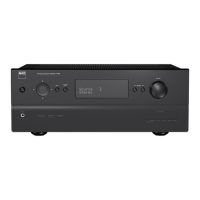
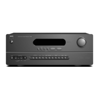
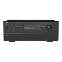
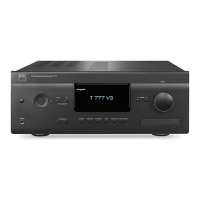
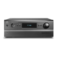
Identification and description of all controls and indicators on the front panel.
Step-by-step guide for disassembling the unit, starting with cover removal.
Procedures for setting idle current and ISC sensitivity for amplifier channels.
Detailed schematics for composite video signal processing.
Schematic for the audio input and output switching circuitry.
Detailed schematics for component video signal processing.
Product name and type.
| Power Output | 5 x 100 W |
|---|---|
| Weight | 20.9 kg |
| Dimensions | 435 x 150 x 380 mm |
| Signal-To-Noise Ratio | 100 dB |
| Total Harmonic Distortion | < 0.03% |
| Input Sensitivity | 200 mV |
| Tuner Bands | AM/FM |
| Preset Station Qty | 30 |
| Digital Sound Processor (DSP) | Yes |
| DSP Presets | 5 |
| Bass Control | Yes |
| Treble Control | Yes |
| HDMI | No |
| Frequency Response | 20 Hz - 20 kHz |
| Surround Sound Formats | Dolby Digital, DTS |
| Input Impedance | 47 kΩ |
| Speaker Impedance | 4 - 8 ohms |
| Amplifier Output Details | 70W x 7 (8 ohms, 20Hz - 20kHz, 0.08% THD) |
| Response Bandwidth | 20Hz - 20kHz |