10
AMPLIFIER ADJUSTMENT
Idle Current
1. Rotate R522 fully clockwise.
2. Connect DC millivoltmeter to P501 (i.e. Across half of R523, 0.22 Ohm resistor).
3. Turn on the unit.
4. Adjust R522 for 1mV reading on voltmeter.
5. Leave power on for at least 5 min, and check for idle current again.
6. Repeat for other channels.
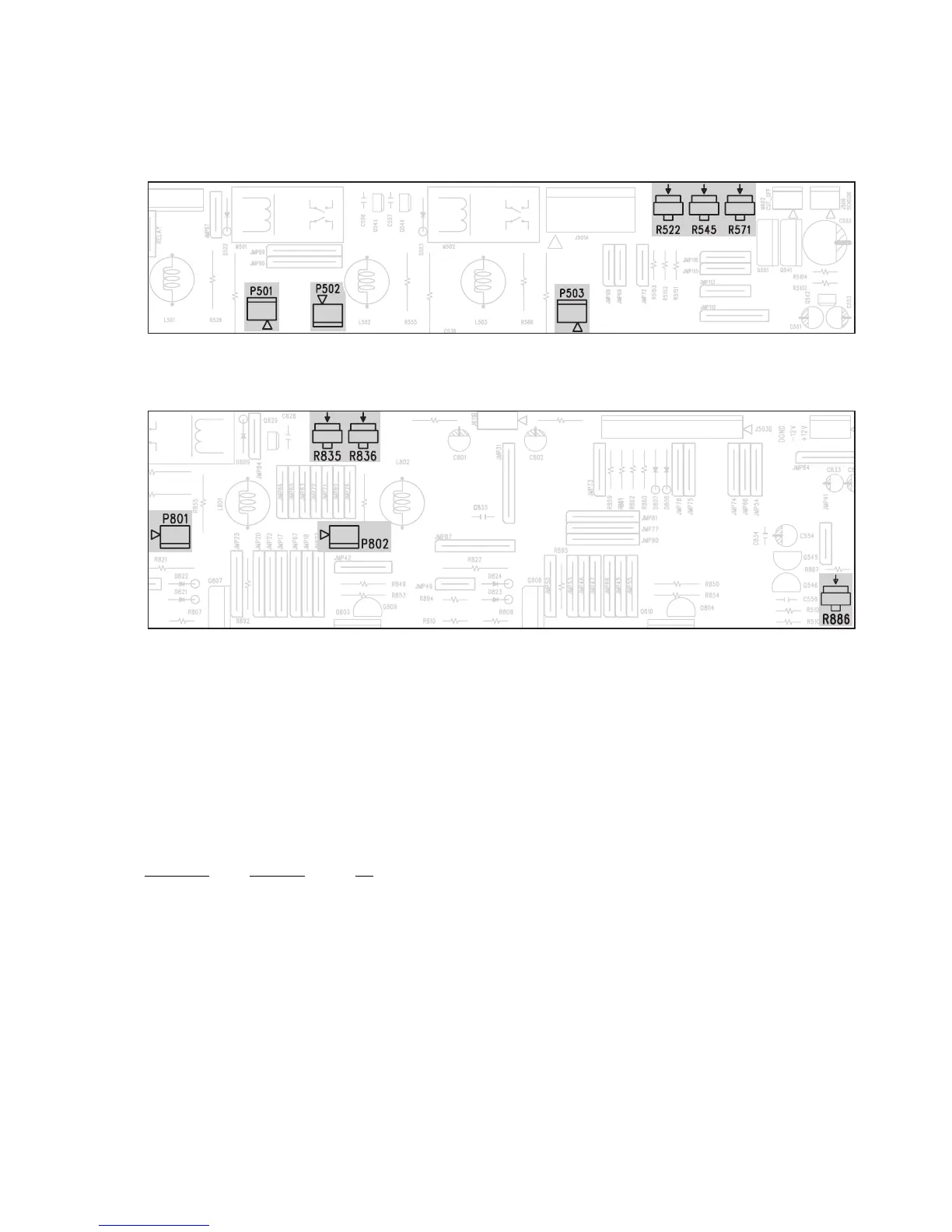
CHANNEL JUMPER VR
FL P503 R571
FR P502 R545
CP501R522
SL P801 R835
SR P802 R836
ISC Sensitivity
1. Connect 8 ohm loading to all channels.
2. Rotate R886 fully clockwise.
3. Load all channels at full power using 1kHz sine wave.
4. At this time, monitor the THD of the output. Clipping should occur before full power achieved.
5. Rotate R886 counter-clockwise slowly until the THD just below 0.1%.
6. The procedure is finish at this step.
7. Load all channels at full power using 1kHz sine wave with 4 ohm load.
8. The clipping power(at THD 0.1%) should less than 85W.
ADJUSTMENT POINT DIAGRAM
FRONT/CENTER AMPLIFIER BOARD
SURROUND AMPLIFIER BOARD