Control Units
FP0
2-18
Matsushita Automation Controls
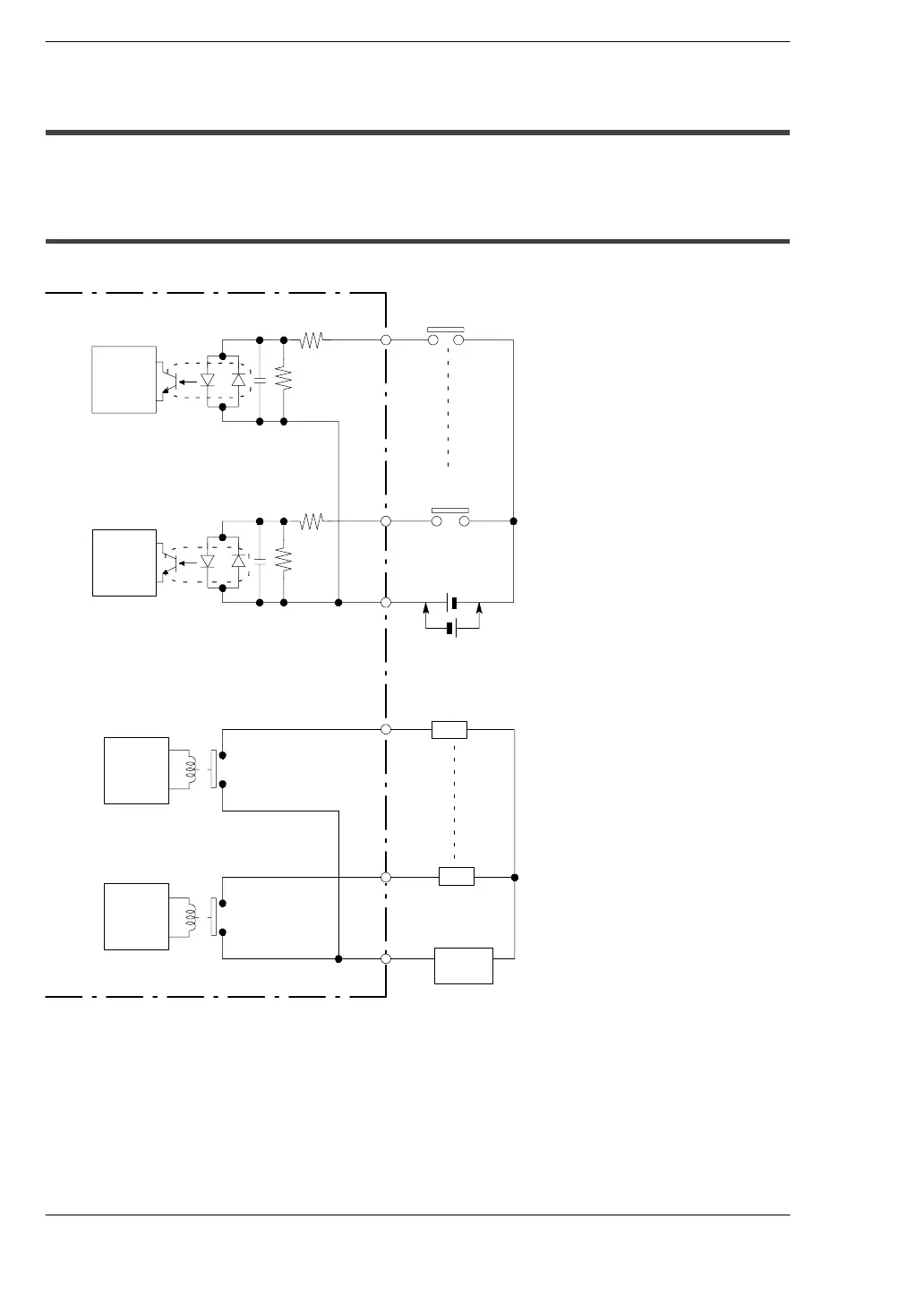
2.3 Internal Circuit Diagram
2.3 Internal Circuit Diagram
2.3.1 Relay Output Type
(C10RS/C 10CRS/C10RM/C 10CRM/C14RS/C14C RS/C14RM/C14C RM)
FP0-C10RS/C10CRS/C10RM/C10CRM/C14RS/C14CRS/C14RM/C14CRM
Internal
circuit
X0
Xn
COM
Y0
Yn
COM
Power
supply
Input side
Output side
5.6 k
Ω
(*
Note 1)
5.6 k
Ω
Internal
circuit
Internal
circuit
Internal
circuit
L
oad
L
oad
(*
Note
1)
24 V DC (
*
Note 2)
.
Notes
D
(
*
1): The resistor in the control unit is 2 k
•
for X0 through X5,
and 1 k
•
for X6 and X7.
D
(
*
2): Either positive or negative polarity is possible for the input
voltage supply.

 Loading...