Control Units
FP0
2-25
Matsushita Automation Controls
2.4 Pin Layouts
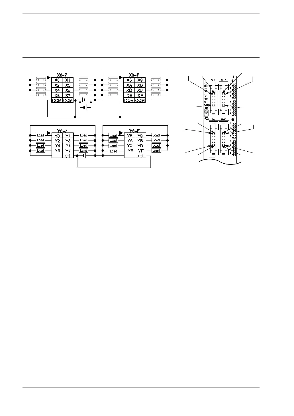
2.4.5 C32T/C32CT
(+)
C32T/C32CT
X8
Y8 Y9
X9
X0 X1
Y1
COM
COM
(-)(+) (+) ( -)
Input Input
Output Output
Y0
(+)
(
*
Note 1)
.
Notes
D
The four COM terminals of input terminals (X0 -7 and X8-F) are
connected internally, however they should be externally
connected as well.
D
The (+) terminals of output terminals (Y0 - 7) and output
terminals (Y8- F) are connected internally, however they
should be externally connected as well.
D
The ( -) terminals of output terminals (Y0-7) and output
terminals (Y8- F) are connected internally, however they
should be externally connected as well.
D
(
*
1): Either positive or negative polarity is possible for the input
voltage supply.

 Loading...