39
W415-1232 / B / 05.15.14
EN
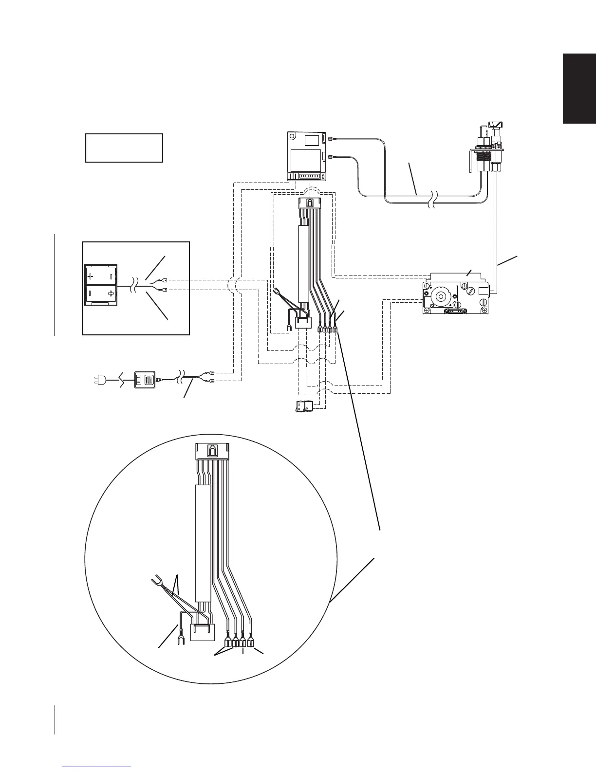
6.7 WIRING DIAGRAM
wall switch or remote control must be installed in a convenient location to operate the main burner. A 20’ (6.1m)
ength of 18 gauge wire is connected to the gas valve wire harness for this wall switch, however, if a greater length
s required route 2-strand (solid core) wire complete with two 1/4” (6.4mm) insulated male quick connects through
he electrical hole located at the bottom left side of the appliance and connect to the wire harness as shown.
BATTERY
HOLDER
PILOT
ASSEMBLY
IGNITION
MODULE
PILOT
G
AS LINE
White
(S)
[through
Gas line
conduit]
Red
Black
NOTE: WIRE TAGS
ARE BRACKETED
AC ADAPTOR
Black (3 Volt)
PTIONAL
O
PILOT
IN
OUT
ADJ
HI
LO
VENT
BlackRedBrown
Black
Black
WIRE
HARNESS
Orange
Grounded to Sheet Metal
Red
Black
MAIN BURNER SWITCH
G
AS VALVE
RACKET
B
NOTE: The battery holder was supplied with your appliance but not connected. In an event of a power
failure, install two 'D' batteries in the holder and attach to wire harness as illustrated above.