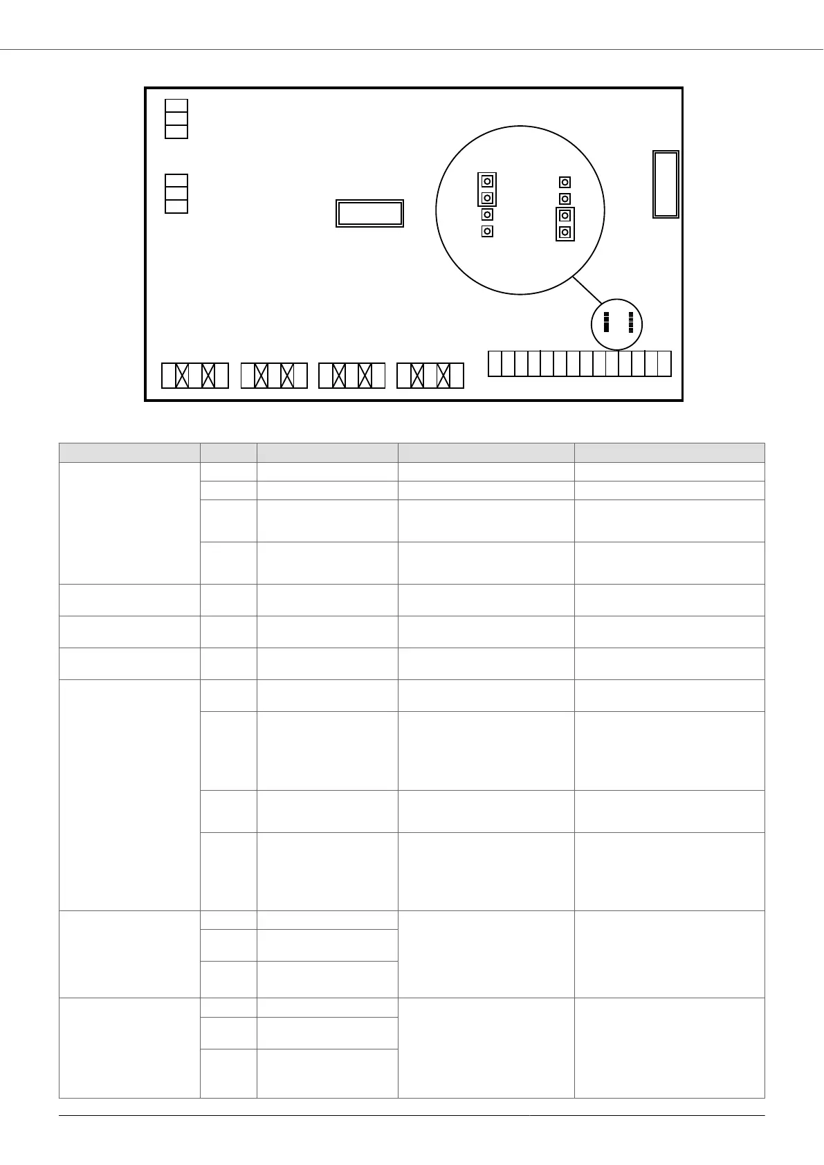
MODBUS
COMBO
DISPLAY
S2-
S2+
G
S1-
S1+
G
NO4
COM4 NC4
NO3
COM3 NC3
NO2
COM2 NC2
NO1
COM1 NC1
DOL 2
DOL 1
ALARM
STATUS
IN4
IN3
IN2
IN1
0V
+15V
0V
+15V
0V
+10V
AN4
AN3
AN2
AN1
4-20mA
0/10V
AN4 SEL
4-20mA
0/10V
AN3 SEL
4-20mA
0/10V
AN4 SEL
4-20mA
0/10V
AN3 SEL
Type Description Functionality Comments
Analog inputs AN1 4-20 mA Sensor 1 -
AN2 4-20 mA Sensor 2 -
AN3 4-20 mA
0-10 V
External set value Configurable as 4-20 mA or 0-10V
via jumper.
AN4 4-20 mA
0-10 V
External frequency
External set value 2
Configurable as 4-20 mA or 0-10V
via jumper.
Power Supply +15V 15 VDC, max 100 mA Power supply for 4-20 mA ana-
log inputs
Do not use as a power supply for
the digital inputs!
Power Supply +10V 10 VDC, max 3 mA Power supply for 0-10 V analog
inputs
Do not use as a power supply for
the digital inputs!
Signal GND 0V Insulated Signal GND for analog and digi-
tal inputs
-
Digital inputs IN1 Active low Motor start and stop Programmable as Normally Open
or Normally Closed.
IN2 Active low Motor start and stop
Switching of set value 1 and 2
Switching of work frequency 1
and 2
Programmable as Normally Open
or Normally Closed.
IN3 Active low Motor start and stop
Switching of sensors 1 and 2
Programmable as Normally Open
or Normally Closed.
IN4 Active low Alarms reset
Motor start and stop
Switch between main and auxili-
ary control modes
Programmable as Normally Open
or Normally Closed.
Relay outputs NO1 Normally Open STATUS relay
NO1, COM1: closed contact
with motor running.
NC1, COM1: closed contact
with motor stopped.
Potential-free contacts
Max 250 VAC, 2 A
Max 30 VDC, 2 A
COM
1
Common
NC1 Normally Closed
Relay outputs NO2 Normally Open ALARM relay
NO2, COM2: closed contact
without alarm.
NC2, COM2: closed contact
with alarm or without power
supply.
Potential-free contacts
Max 250 VAC, 2 A
Max 30 VDC, 2 A
COM
2
Common
NC2 Normally Closed
VASCO - VAriable Speed COntroller
31