If the maximum flow rate required is 60 l/min, it is sufficient to use a 6 liter pressure vessel.
The pre-charge pressure of the pressure vessel must be approx. 80% of the operating pressure.
Example
If the set pressure in the inverter is 4 bar, the pre-charge pressure of the pressure vessel should be approx. 3.2 bar.
NOTE
The pre-charge pressure must be adjusted with the system completely unloaded.
10.3. Electrical connections
The device may be connected to linear pressure sensors with 4 - 20 mA output. The supply voltage range of the
sensor must be such as to include the 15 V DC voltage with which the device feeds the analog inputs.
The pressure sensor is connected via the terminals of the analogue input 1, i.e:
• AN1: 4-20 mA signal (-)
• +15V: 15 VDC power supply (+)
The device supports the installation of a second pressure sensor for:
• Operating at constant differential pressure (read the dedicated chapter).
• Automatic replacement of the main pressure sensor in case of failure.
• Exchange of active pressure sensor via digital input.
The secondary pressure sensor is connected via the terminals of the analogue input 2, i.e:
• AN2: 4-20 mA signal (-)
• +15V: 15 VDC power supply (+)
11. Splitting the pumping system
11.1. Introduction.
When the variation in water demand is considerable, it is a good idea to split the pumping unit into several units to
ensure greater efficiency and reliability.
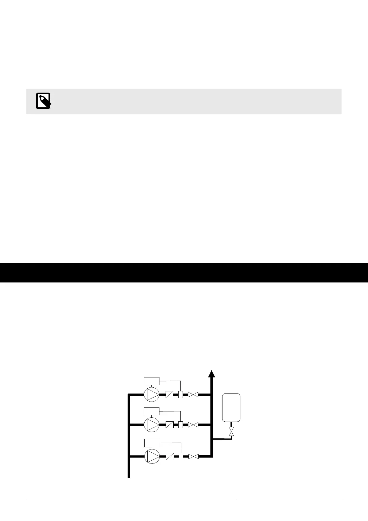
A splitting method (called COMBO mode) consists in using several pumps in parallel (up to 8) each controlled by
an inverter.
In this case, the efficiency and reliability of the pumping unit is maximized, ensuring soft starts and stops and
complete protection of the pumps. The alternation of operation also allows to even out the wear of the pumps and,
in case of failure of a pump or an inverter, the remaining units of the group can continue their operation.
1: Inverter; 2: Pump; 3: Check valve; 4: Pressure vessel; 5: Gate valve; 6: Gate valve; 7: Pressure sensor
VASCO - VAriable Speed COntroller
44