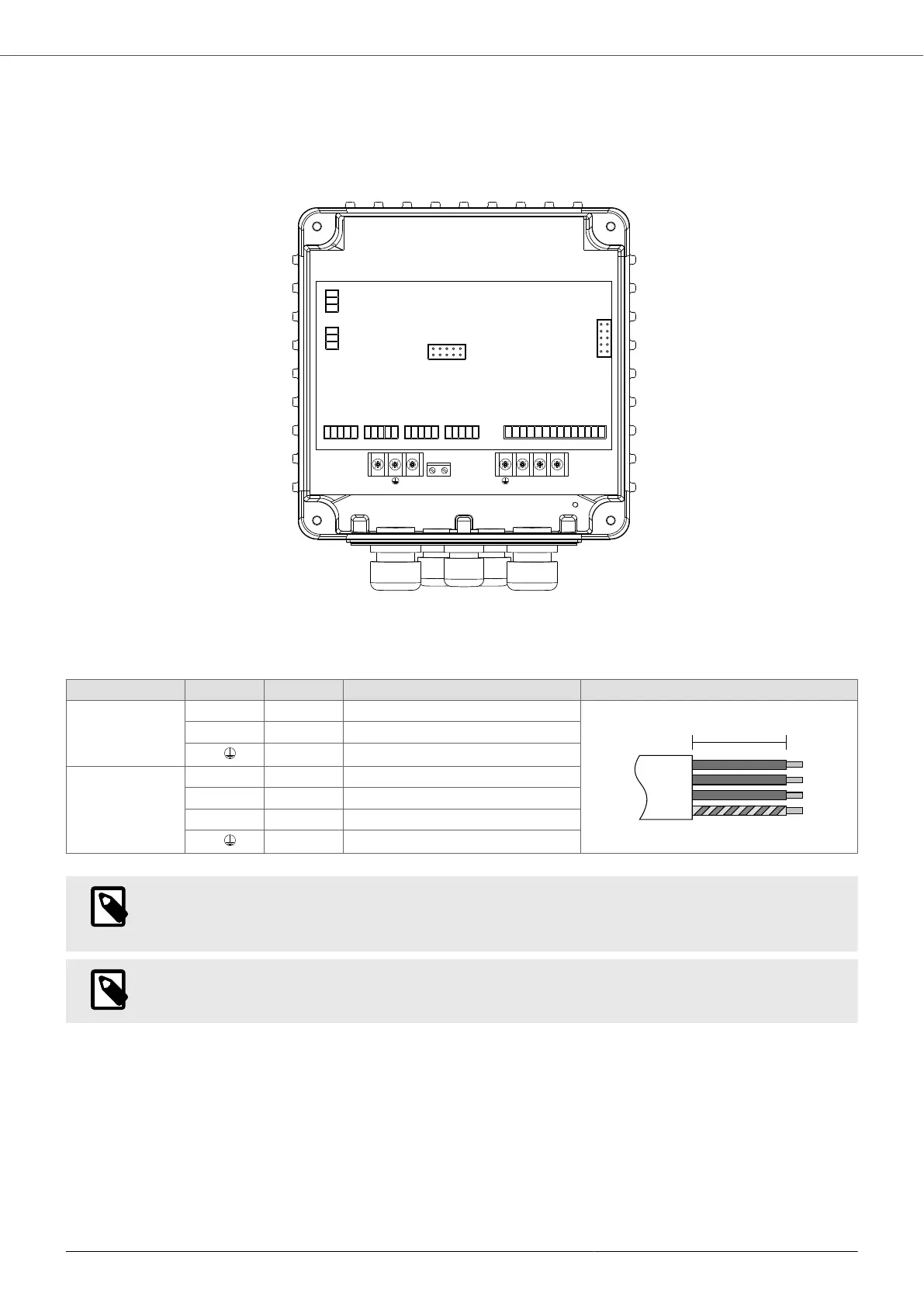
7.5.1. Power connections
V209 , V214
L1
LINE
(L) (N)
L2
V
U
W
MOTOR
F1 F2
FAN
A [mm] Pre-insulated cable lug Stripping diagram
Power Supply
LINE
L1/L 35 Fork for M4 screw
L2/N 35 Fork for M4 screw
P.E.
35 Fork for M4 screw
Motor
MOTOR
U 35 Fork for M4 screw
V 35 Fork for M4 screw
W 35 Fork for M4 screw
P.E.
35 Fork for M4 screw
NOTE
When connecting a single-phase PSC motor (capacitor permanently inserted), connect the start to
phase U and the common to phase V, leaving phase W unconnected.
NOTE
The FAN terminal: F1, F2 powers the 230 VAC auxiliary fan supplied in the wall kit.
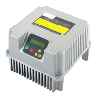
VASCO - VAriable Speed COntroller
24