PILOT 325 3x230V , PILOT 325 3x400V , PILOT 325 3x460V , PILOT 330 3x230V , PILOT
330 3x400V , PILOT 330 3x460V
1
L1
3
L2
5
L3
13
NO
A1
A2
T1
2
T2
4
T3
6
14
A1
A2
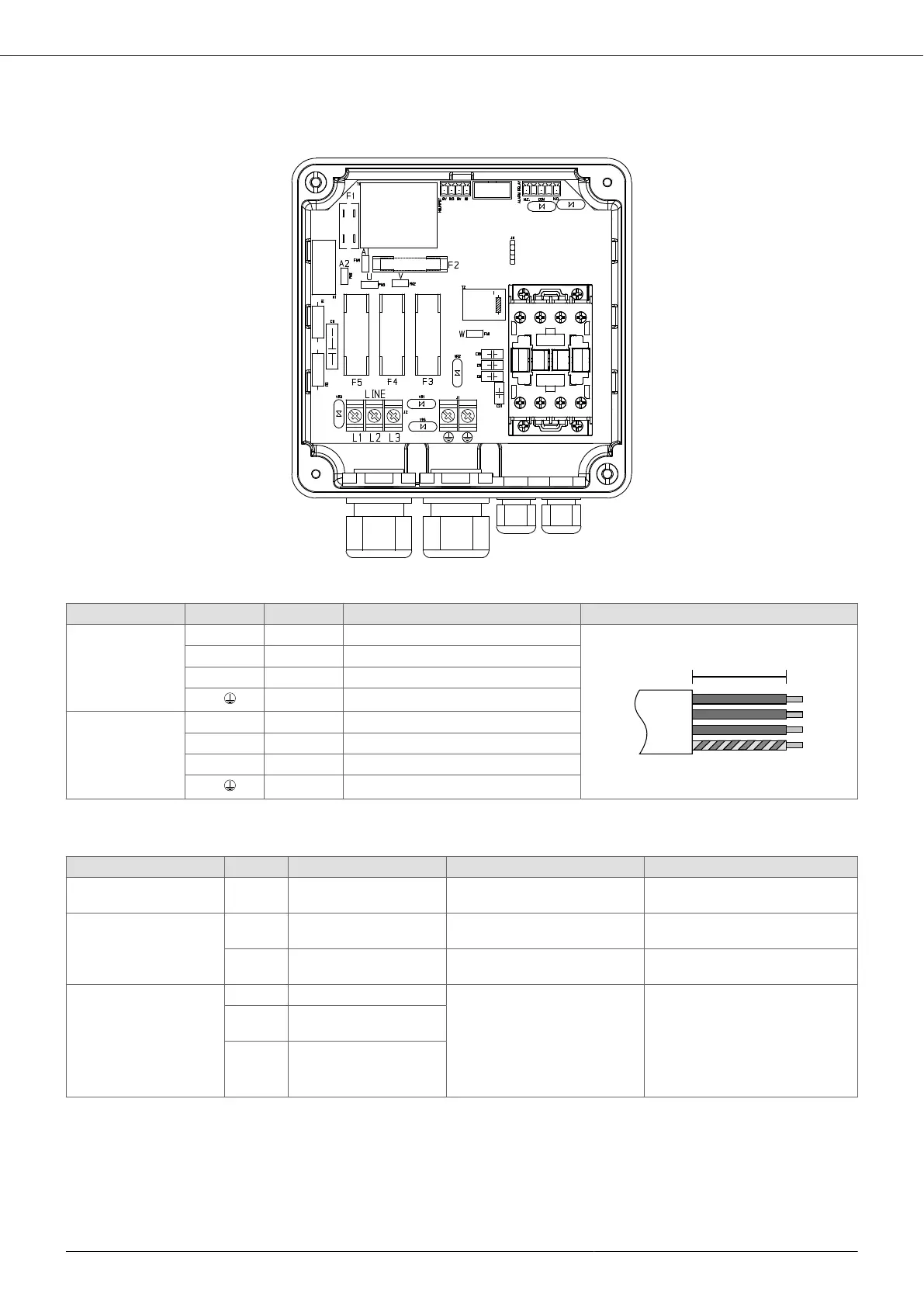
A [mm] Pre-insulated cable lug Stripping diagram
Power Supply
LINE
L1 50 Fork for M4 screw
L2 50 Fork for M4 screw
L3 50 Fork for M4 screw
P.E.
50 Fork for M4 screw
Motor
MOTOR
T1 70 Fork for M4 screw
T2 70 Fork for M4 screw
T3 70 Fork for M4 screw
P.E.
70 Fork for M4 screw
7.4.2. Control connections
Type Description Functionality Comments
Signal GND 0V Insulated Signal GND for analog and digi-
tal inputs
-
Digital inputs IN1 Active low Motor start and stop Programmable as Normally Open
or Normally Closed.
IN2 Active low Motor start and stop Programmable as Normally Open
or Normally Closed.
Relay outputs NO2 Normally Open ALARM relay
NO2, COM2: closed contact
without alarm.
NC2, COM2: closed contact
with alarm or without power
supply.
Potential-free contacts
Max 250 VAC, 2 A
Max 30 VDC, 2 A
COM
2
Common
NC2 Normally Closed
7.4.3. Circuit board installation AVIATOR
The circuit board AVIATOR allows increasing the starting torque of single-phase motors in a simple and economical
way. AVIATORIt can be ordered as an accessory for PILOT 118 1x230V, is equipped with specific contacts with
which it is mechanically and electrically coupled to the power board of the PILOT. The starting capacitor, present
in the board AVIATOR, is inserted in parallel with the run capacitor only in the starting phase of the motor.
Subsequently, when the motor has started, AVIATOR it disconnects the starting capacitor.
PILOT
17