© National Instruments Corporation 9 SCXI Quick Start Guide
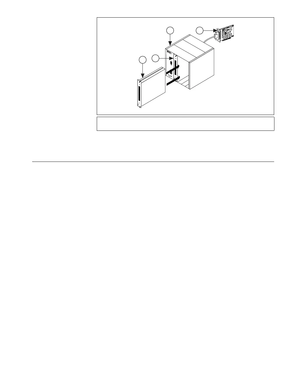
Figure 7. Installing the SCXI Module in an Existing System
Step 5. Attach Sensors and Signal Lines
Wire sensors and signal lines to the terminal block, accessory, or module
terminals. Helpful information is available as follows:
• Signal and terminal connections:
– You can view and print a connection diagram for NI-DAQmx
tasks and virtual channels in your system through the DAQ
Assistant. Select the task or virtual channel and click the
Connection Diagram tab. Select each virtual channel in the task
to view the terminal names and numbers for connections from
sensor to connector block.
– Module and accessory documentation is on the Device Document
Browser.
– Pin assignments also are located in the Device Terminals topics
of the Measurement and Automation Explorer Help for
NI-DAQmx and Measurement and Automation Explorer for
Traditional NI-DAQ, both accessible from the MAX Help menu.
• Switch or jumper settings—Refer to the module user manual for more
information about configuring the hardware.
•Sensors:
– Refer to
ni.com/sensors.
– If you are using LabVIEW, refer to the LabVIEW Measurements
Manual packaged with LabVIEW or available from
ni.com/manuals.
1 New SCXI Module
2 Existing SCXI Module
3 SCXI Chassis
4 Existing DAQ Device
O
N
8
1
2
3
4
5
6
7
1
2
9
1
0
1
1
ADDRESS
BAUD
1
3
2
4
 Loading...