Appendix A Device-Specific Information
© National Instruments Corporation A-79 M Series User Manual
USER 1 and USER 2
The USER 1 and USER 2 BNC connectors allow you to use a BNC
connector for a digital or timing I/O signal of your choice. The USER 1 and
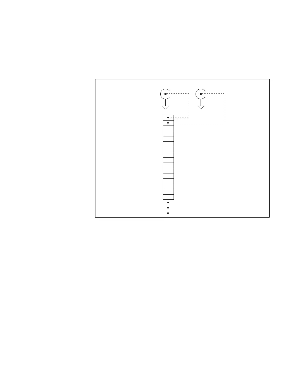
USER 2 BNC connectors are routed (internal to the USB-6251 BNC) to the
USER 1 and USER 2 screw terminals, as shown in Figure A-37.
Figure A-37. USER <1..2> BNC Connections
USER 2 BNC
D GND
USER 1
P0.6
P0.5
P0.4
D GND
P0.3
P0.2
P0.1
P0.0
D GND
+5 V
D GND
USER 2
PFI 8/P2.0
P0.7
D GND
Internal Connection
USER 1 BNC
D GND
Screw
Terminal
Block

 Loading...