Appendix A Device-Specific Information
© National Instruments Corporation A-121 M Series User Manual
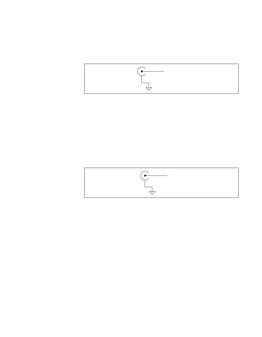
Digital I/O and Timing I/O
You can access digital I/O and timing I/O signals on the BNC connectors
labeled PFI <0..7>/P1.<0..7>. Figure A-51 shows the DIO/TIO circuitry on
the USB-6259 BNC.
Figure A-51. Digital I/O and Timing I/O Circuitry
Refer to the Connecting Digital I/O Signals section of Chapter 6, Digital
I/O, and the Connecting PFI Input Signals section of Chapter 8, PFI, for
more information.
APFI
You can access the analog programmable function interface signals on the
BNC connectors labeled APFI <0..1>. Figure A-52 shows the APFI
circuitry on the USB-6259 BNC.
Figure A-52. Analog Programmable Function Interface Circuitry
Refer to the Triggering with an Analog Source section of Chapter 11,
Triggering, for more information.
PFI
x
/P1.
D GND
APFI
AI GND

 Loading...