Appendix B Timing Diagrams
M Series User Manual B-38 ni.com
Input Requirements
Refer to the Figure B-41 for the M Series counter/timer circuitry.
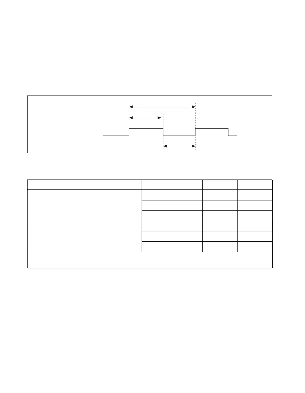
Source Period and Pulse Width
Figure B-46 and Table B-30 show the timing requirements for Counter n
Source. The requirements depend on the synchronization mode.
Figure B-46. Counter n Source Timing Requirements
Table B-30. Counter n Source Timing
Time Description Synchronization Mode Min (ns)
*
Max (ns)
t
5
Counter n Source Period 80 MHz Source 12.5 —
Other Internal Source 25.0 —
External Source 50.0 —
t
6
Counter n Source Pulse Width 80 MHz Source 6.2 —
Other Internal Source 12.5 —
External Source 16.0 —
*
The times in this table are measured at the pin of the M Series device. For example, t
5
specifies the minimum period of a
signal driving a PFI, RTSI, or PXI_STAR pin when that signal is internally routed to Counter n Source.
Counter
n
Source
t
5
t
6
t
6

 Loading...