Appendix B Timing Diagrams
M Series User Manual B-42 ni.com
Output Delays
Refer to the Figure B-41 for the M Series counter/timer circuitry.
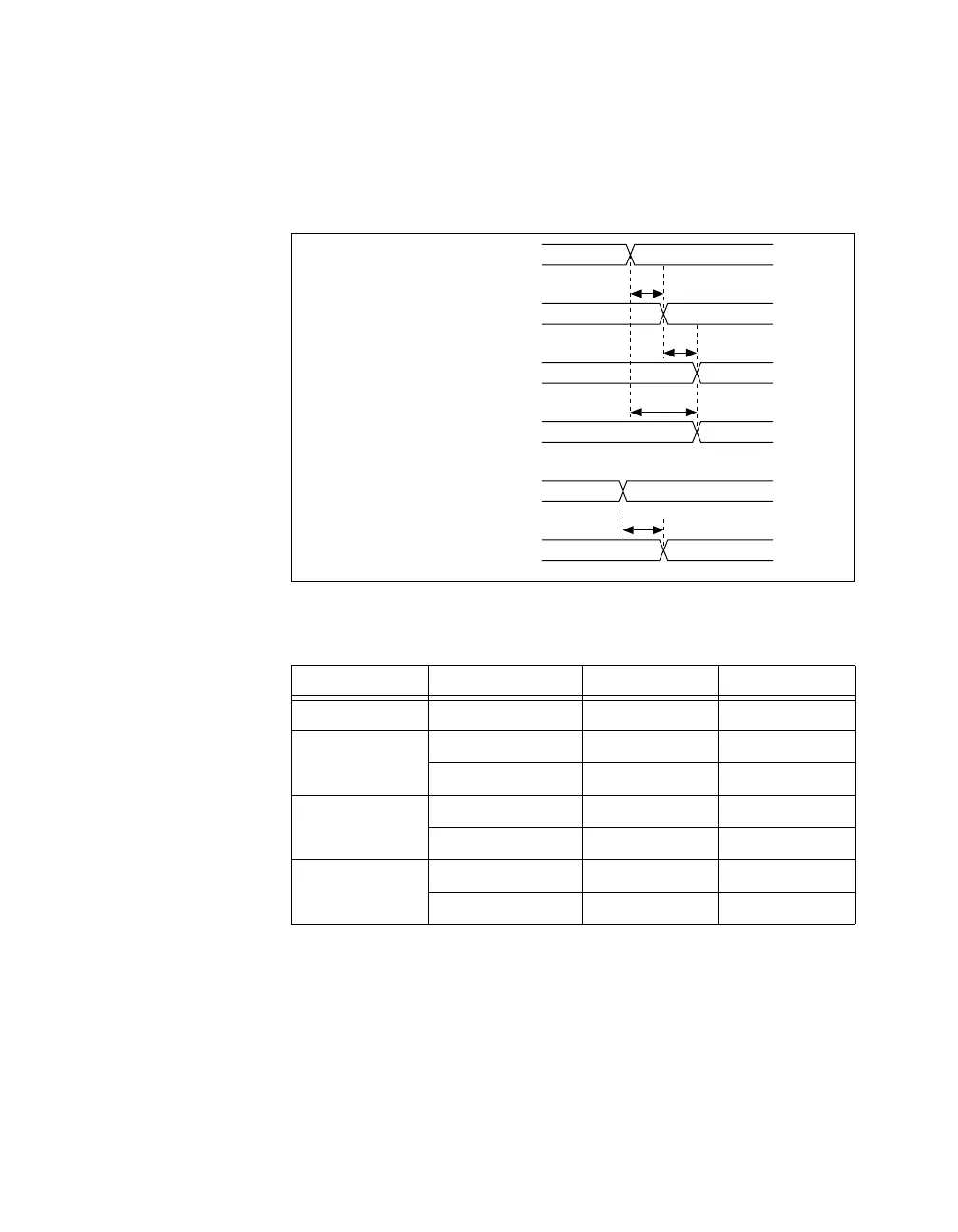
Figure B-50 and Table B-34 show the output delays.
Figure B-50. Output Delays
Table B-34. Output Delays Timing
Time Line Min (ns) Max (ns)
t
10
— 1.0 4.0
t
11
PFI 7.5 28.2
RTSI 6.5 18.0
t
12
PFI 8.5 32.2
RTSI 7.5 22.0
t
13
PFI 7.5 28.7
RTSI 6.5 18.0
t
10
t
11
t
12
t
13
Selected Source
PFI, RTSI
(Counter
n
Gate)
Selected Gate
PFI, RTSI
(Counter
n
Source)
PFI, RTSI
(Counter
n
Internal Out)
Out_o
 Loading...