Chapter 4 Analog Input
M Series User Manual 4-18 ni.com
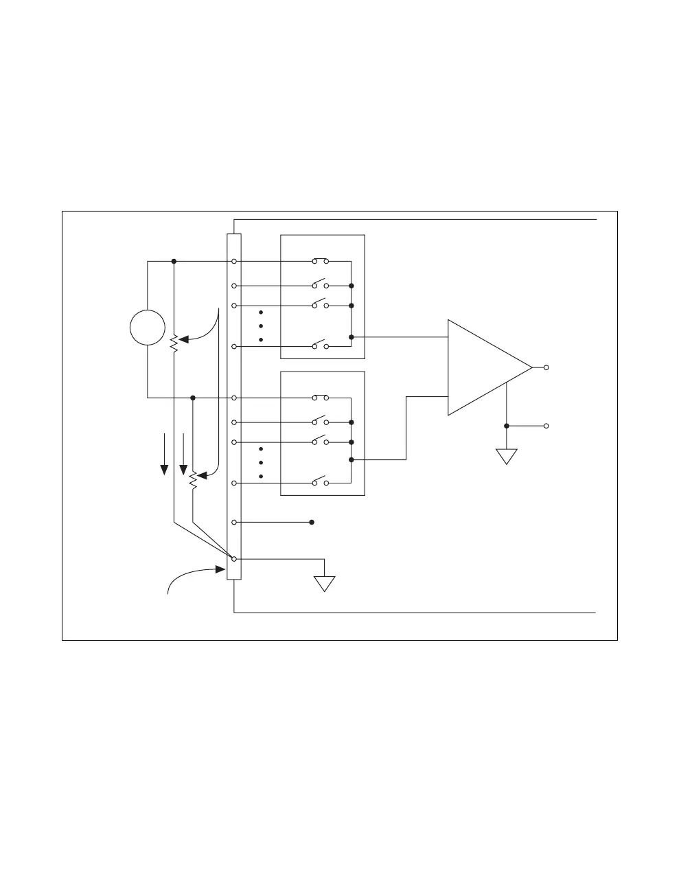
You can fully balance the signal path by connecting another resistor of
the same value between the positive input and AI GND, as shown in
Figure 4-6. This fully balanced configuration offers slightly better noise
rejection, but has the disadvantage of loading the source down with the
series combination (sum) of the two resistors. If, for example, the source
impedance is 2 kΩ and each of the two resistors is 100 kΩ, the resistors
load down the source with 200 kΩ and produce a –1% gain error.
Figure 4-6. Differential Connections for Floating Signal Sources
with Balanced Bias Resistors
Both inputs of the NI-PGIA require a DC path to ground in order for the
NI-PGIA to work. If the source is AC coupled (capacitively coupled), the
NI-PGIA needs a resistor between the positive input and AI GND. If the
source has low-impedance, choose a resistor that is large enough not to
significantly load the source but small enough not to produce significant
input offset voltage as a result of input bias current (typically 100 kΩ to
M Series Device Confi
ured in DIFF Mode
PGIA
–
+
–
+
–
+
Floating
Signal
Source
Bias
Current
Return
Paths
AI GND
AI SENSE
Input Multiplexers
Measured
Voltage
Instrumentation
Amplifier
AI+
AI–
I/O Connector
Bias
Resistors
(see text)
V
s
V
m

 Loading...