Chapter 9 Counters
© National Instruments Corporation 9-23 NI USB-621x User Manual
Frequency Generation
You can generate a frequency by using a counter in pulse train generation
mode or by using the frequency generator circuit.
Using the Frequency Generator
The frequency generator can output a square wave at many different
frequencies. The frequency generator is independent of the two
general-purpose 32-bit counter/timer modules on M Series devices.
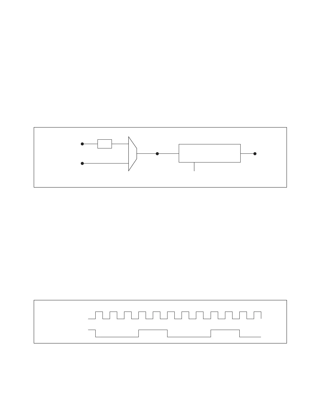
Figure 9-26 shows a block diagram of the frequency generator.
Figure 9-26. Frequency Generator Block Diagram
The frequency generator generates the Frequency Output signal. The
Frequency Output signal is the Frequency Output Timebase divided by a
number you select from 1 to 16. The Frequency Output Timebase can be
either the 20 MHz Timebase divided by 2 or the 100 kHz Timebase.
The duty cycle of Frequency Output is 50% if the divider is either 1 or an
even number. For an odd divider, suppose the divider is set to D. In this
case, Frequency Output is low for (D + 1)/2 cycles and high for (D – 1)/2
cycles of the Frequency Output Timebase.
Figure 9-27 shows the output waveform of the frequency generator when
the divider is set to 5.
Figure 9-27. Frequency Generator Output Waveform
100 kHz Timebase
20 MHz Timebase
Frequency
Output
Timebase
FREQ OUT
Divisor
(1–16)
Frequency Generator
÷
2
Frequency
Output
Timebase
FREQ OUT
(Divisor = 5)

 Loading...


