Chapter 4 Analog Input
NI USB-621x User Manual 4-4 ni.com
The AI ground-reference setting determines how you should connect your
AI signals to the NI 621x device. Refer to Chapter 5, Connecting AI Signals
on the USB-6210/6211 Devices, section for more information.
Ground-reference settings are programmed on a per-channel basis. For
example, you might configure the device to scan 12 channels—four
differentially-configured channels and eight single-ended channels.
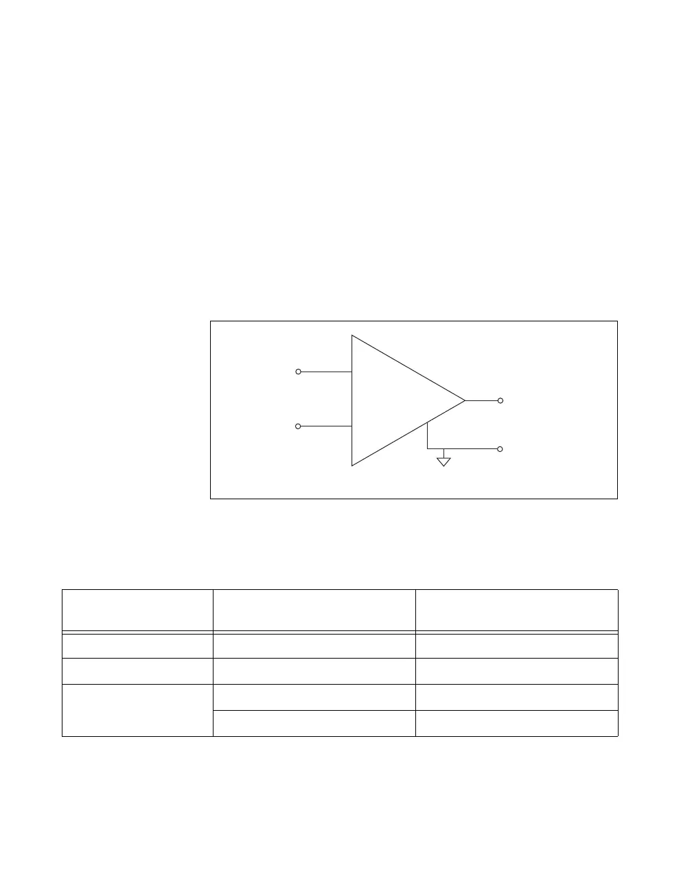
NI 621x devices implement the different analog input ground-reference
settings by routing different signals to the NI-PGIA. The NI-PGIA is a
differential amplifier. That is, the NI-PGIA amplifies (or attenuates) the
difference in voltage between its two inputs. The NI-PGIA drives the ADC
with this amplified voltage. The amount of amplification (the gain), is
determined by the analog input range, as shown in Figure 4-2.
Figure 4-2. NI-PGIA
Table 4-3 shows how signals are routed to the NI-PGIA.
For differential measurements, AI 0 and AI 8 are the positive and negative
inputs of differential analog input channel 0. For a complete list of signal
Table 4-3. Signals Routed to the NI-PGIA
AI Ground-Reference
Settings
Signals Routed to the Positive
Input of the NI-PGIA (V
in+
)
Signals Routed to the Negative
Input of the NI-PGIA (V
in–
)
RSE AI <0..31> AI GND
NRSE AI <0..31> AI SENSE
DIFF AI <0..7> AI <8..15>
AI <16..23> AI <24..31>
V
in+
V
m
= [V
in+
– V
in–
] × Gain
V
m
V
in–
PGIA
+
–
Measured
Voltage
Instrumentation
Amplifier

 Loading...


