Chapter 4 Analog Input
NI USB-621x User Manual 4-16 ni.com
to AI Convert Clock Signal for more information about the timing
requirements between ai/ConvertClock and ai/SampleClock.
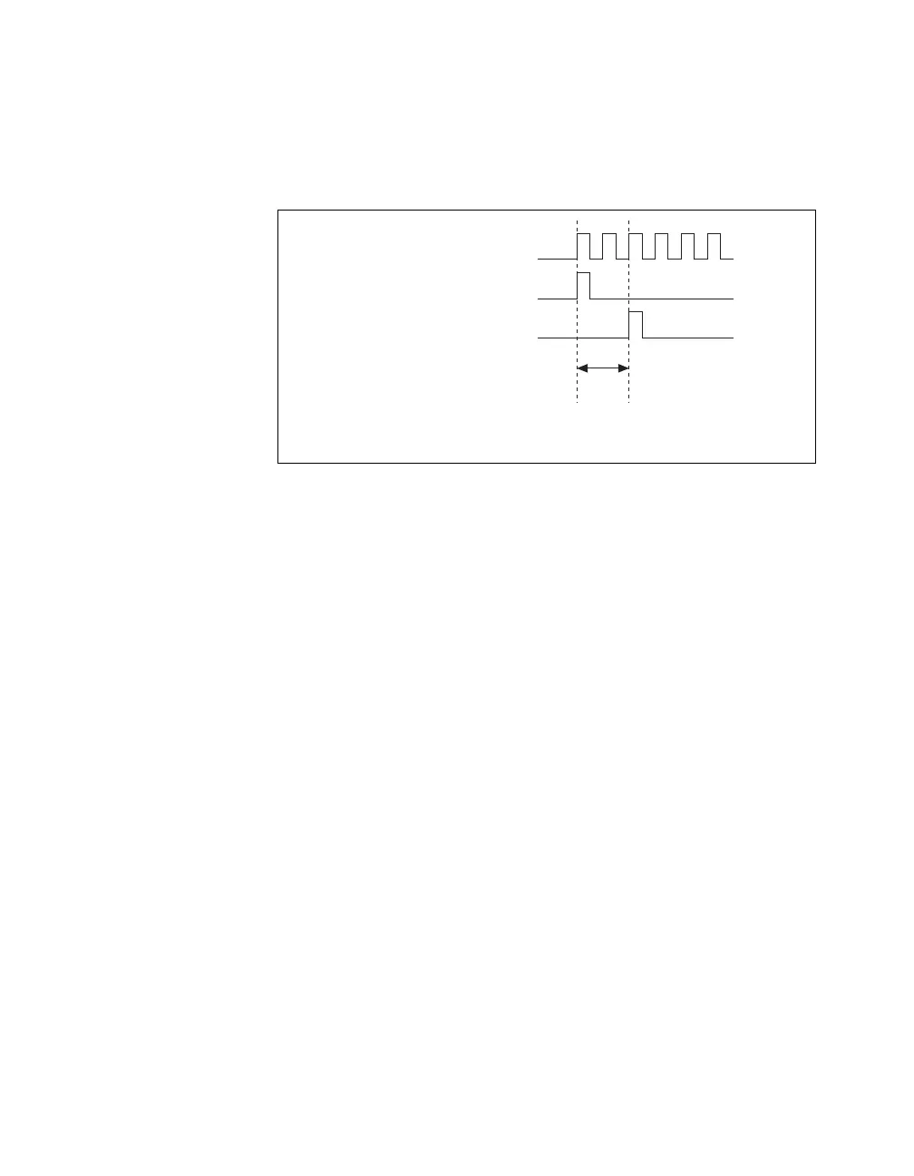
Figure 4-8 shows the relationship of ai/SampleClock to ai/StartTrigger.
Figure 4-8. ai/SampleClock and ai/StartTrigger
AI Sample Clock Timebase Signal
You can route any of the following signals to be the AI Sample Clock
Timebase (ai/SampleClockTimebase) signal:
• 20 MHz Timebase
• 100 kHz Timebase
• PFI <0..3>, PFI <8..11>
ai/SampleClockTimebase is not available as an output on the I/O connector.
ai/SampleClockTimebase is divided down to provide one of the possible
sources for ai/SampleClock. You can configure the polarity selection for
ai/SampleClockTimebase as either rising or falling edge.
AI Convert Clock Signal
Use the AI Convert Clock (ai/ConvertClock) signal to initiate a single A/D
conversion on a single channel. A sample (controlled by the AI Sample
Clock) consists of one or more conversions.
You can specify either an internal or external signal as the source of
ai/ConvertClock. You also can specify whether the measurement sample
begins on the rising edge or falling edge of ai/ConvertClock.
By default, NI-DAQmx chooses the fastest conversion rate possible based
on the speed of the A/D converter and adds 10 µs of padding between each
ai/SampleClockTimebase
ai/StartTrigger
ai/SampleClock
Delay
From
Start
Trigger

 Loading...


