© National Instruments Corporation 8-1 NI USB-621x User Manual
8
Digital I/O
NI 621x devices have eight static digital input lines, P0.<0..7>. These lines
also can be used as PFI inputs.
NI 621x devices have eight static digital output lines, P1.<0..8>.These lines
also can be used as PFI output. By default the digital output lines are
disabled (high impedance with a 47 kΩ pull down resistor) on power up.
Software can enable or disable the entire port (software cannot enable
individual lines). Once the port is enabled, you can individually configure
each line to the following:
• Set a line to a static 0
• Set a line to a static 1
• Export a timing output signal to a line as a PFI pin
The voltage input and output levels and the current drive level of the DI and
DO lines are listed in the NI 621x Specifications. Refer to Chapter 10, PFI,
for more information on PFI inputs and outputs.
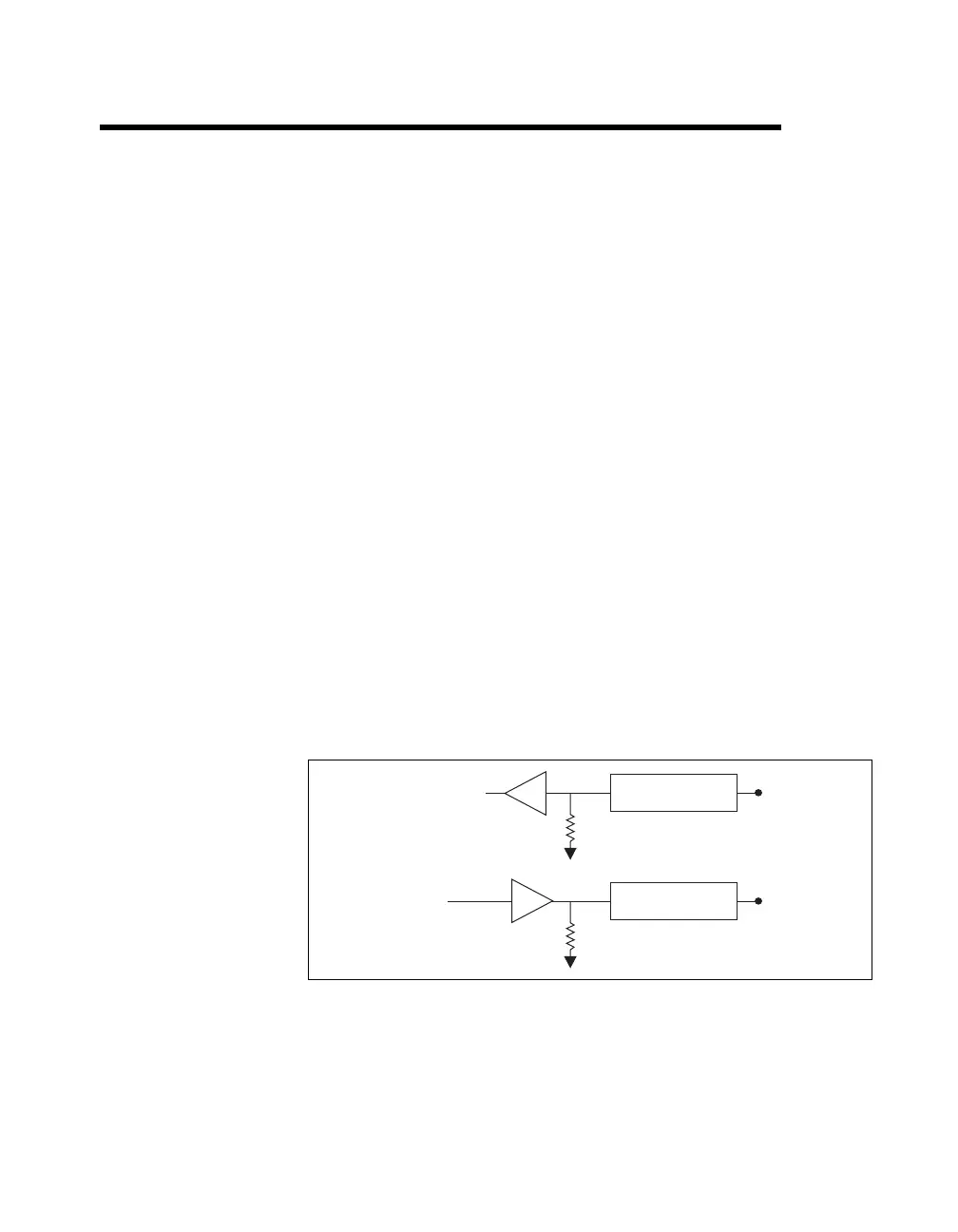
Figure 8-1 shows the circuitry of one DI line and one DO line. The
following sections provide information about the various parts of the DIO
circuit.
Figure 8-1. M Series Digital I/O Circuitry
The DI terminals are named P0.<0..7> on the NI 621x device I/O connector.
The DO terminals are named P1.<0..7> on the NI 621x device I/O
connector.
Static DI
I/O Protection
47kΩ Pull-Down
P0.
I/O Protection
47 kΩ Pull-Down
P1.
Static DO

 Loading...


