© National Instruments | 8-5
X Series User Manual
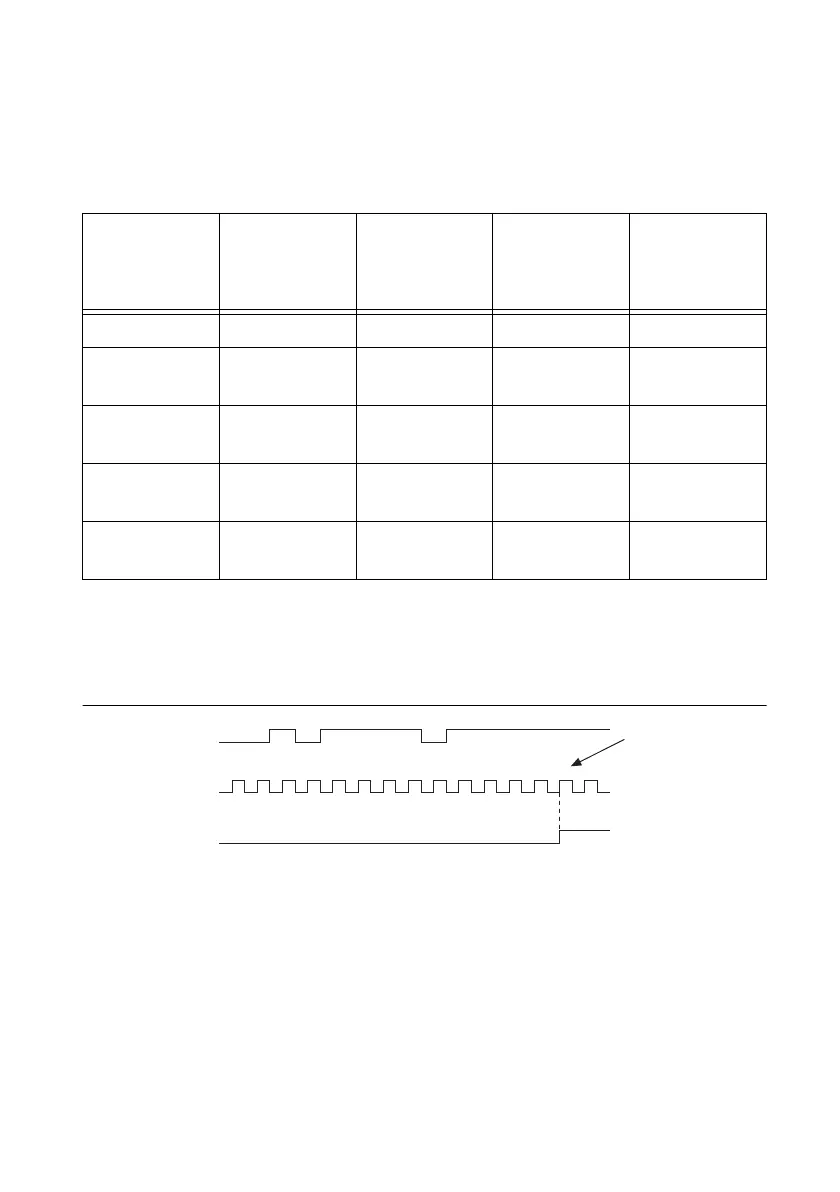
Assume that an input terminal has been low for a long time. The input terminal then changes
from low to high, but glitches several times. When the filter clock has sampled the signal high
on N consecutive edges, the low to high transition is propagated to the rest of the circuit. The
value of N depends on the filter setting; refer to Table 8-1.
The filter setting for each input can be configured independently. On power up, the filters are
disabled. Figure 8-3 shows an example of a low to high transition on an input that has a custom
filter set to N = 5.
Figure 8-3. Filter Example
Enabling filters introduces jitter on the input signal. The maximum jitter is one period of the
timebase.
When a RTSI input is routed directly to PFI, the X Series device does not use the filtered version
of the input signal.
Table 8-1. Filters
Filter Setting Filter Clock
N (Filter
Clocks
Needed to
Pass Signal)
Pulse Width
Guaranteed
to Pass Filter
Pulse Width
Guaranteed
to Not Pass
Filter
None — — — —
90 ns
(short)
100 MHz 9 90 ns 80 ns
5.12 µs
(medium)
100 MHz 512 5.12 µs 5.11 µs
2.56 ms
(high)
100 kHz 256 2.56 ms 2.55 ms
Custom User
configurable
N N/timebase (N - 1)/
timebase
12314123 45
RTSI, PFI, or
PXI_STAR Terminal
Filtered input goes
high when terminal
is sampled high on
five consecutive filter
clocks.
Filter Clock
Filtered Input
 Loading...


