8-4 | ni.com
Chapter 8 PFI
Using PFI Terminals to Digital Detection Events
Each PFI can be configured to detect digital changes. The values on the PFI lines cannot be read
in a hardware-timed task, but they can be used to fire the change detection event. For example,
if you wanted to do change detection on eight timed DIO lines but wanted to ensure that the value
of the lines was updated every second independent of the eight lines changing you could set a
PFI line up for change detection and connect a 1 Hz signal to it.
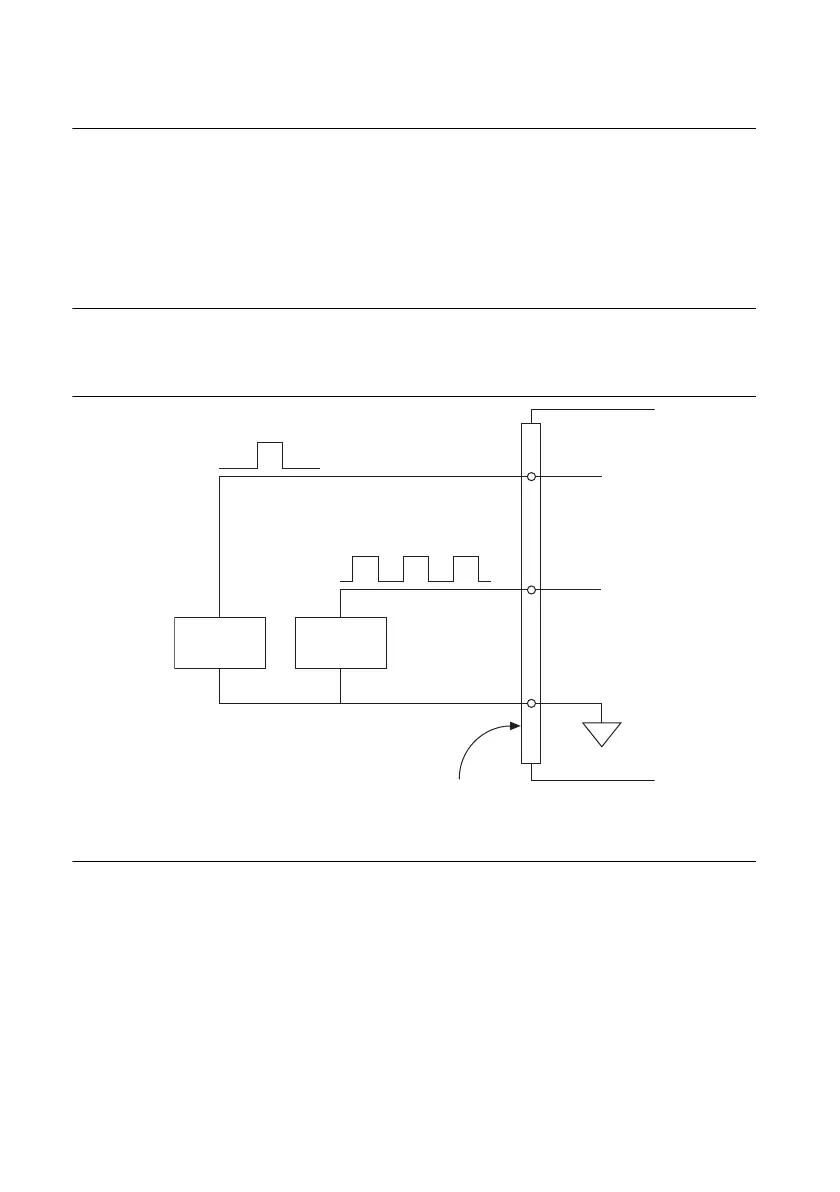
Connecting PFI Input Signals
All PFI input connections are referenced to D GND. Figure 8-2 shows this reference, and how
to connect an external PFI 0 source and an external PFI 2 source to two PFI terminals.
Figure 8-2. PFI Input Signal Connections
PFI Filters
You can enable a programmable debouncing filter on each PFI, RTSI, PXI_STAR, or
PXIe_DSTAR<A,B> signal. When the filters are enabled, your device samples the input on each
rising edge of a filter clock. X Series devices use an onboard oscillator to generate the filter
clock.
The following is an example of low to high transitions of the input signal. High-to-low
transitions work similarly.
PFI 0
Source
PFI 2
Source
X Series Device
D GND
PFI 2
PFI 0
I/O Connector
 Loading...


