3-2 | ni.com
Chapter 3 Connector and LED Information
I/O Connector Signal Descriptions
Table 3-1 describes the signals found on the I/O connectors. Not all signals are available on all
devices.
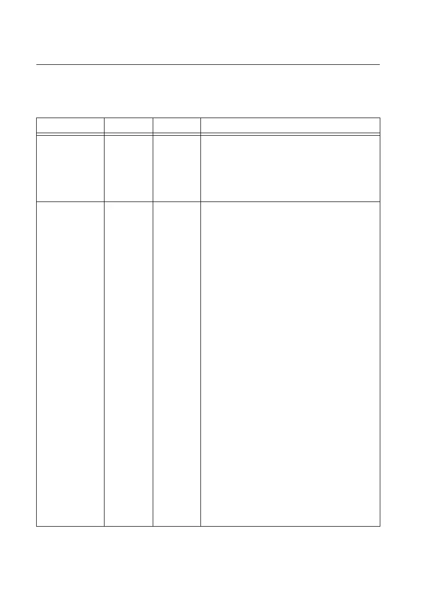
Table 3-1. I/O Connector Signals
Signal Name Reference Direction Description
AI GND — — Analog Input Ground—These terminals are the
reference point for single-ended AI measurements in
RSE mode and the bias current return point for DIFF
measurements. All three ground
references—AI GND, AO GND, and D GND—are
connected on the device.
*
AI <0..207> Var ies Input Analog Input Channels 0 to 207
(MIO X Series Devices) For single-ended
measurements, each signal is an analog input voltage
channel. In RSE mode, AI GND is the reference for
these signals. In NRSE mode, the reference for each
AI <0..15> signal is AI SENSE; the reference for
each AI <16..79> signal is AI SENSE 2; the
reference for each AI <80..143> is AI SENSE 3; and
the reference for each AI <144..207> is
AI SENSE 4.
For differential measurements on MIO X Series
devices, AI 0 and AI 8 are the positive and negative
inputs of differential analog input channel 0.
Similarly, the following signal pairs also form
differential input channels:
AI <1,9>, AI <2,10>, AI <3,11>, AI <4,12>,
AI <5,13>, AI <6,14>, AI <7,15>, AI <16,24>,
AI <17,25>, AI <18,26>, AI <19,27>, AI <20,28>,
AI <21,29>, AI <22,30>, AI <23,31> and so on.
Also refer to the
Connecting Ground-Referenced
Signal Sources
section of Chapter 4, Analog Input.
(Simultaneous MIO X Series Devices) For
differential measurements on Simultaneous MIO
X Series devices, AI 0+ and AI 0- are the positive
and negative inputs of differential analog input
channel 0.
Also refer to the
Connecting Analog Input Signals
section of Chapter 4,
Analog Input.

 Loading...


