© National Instruments | 1-3
PXIe-8840 User Manual
PXIe-8840 Functional Description
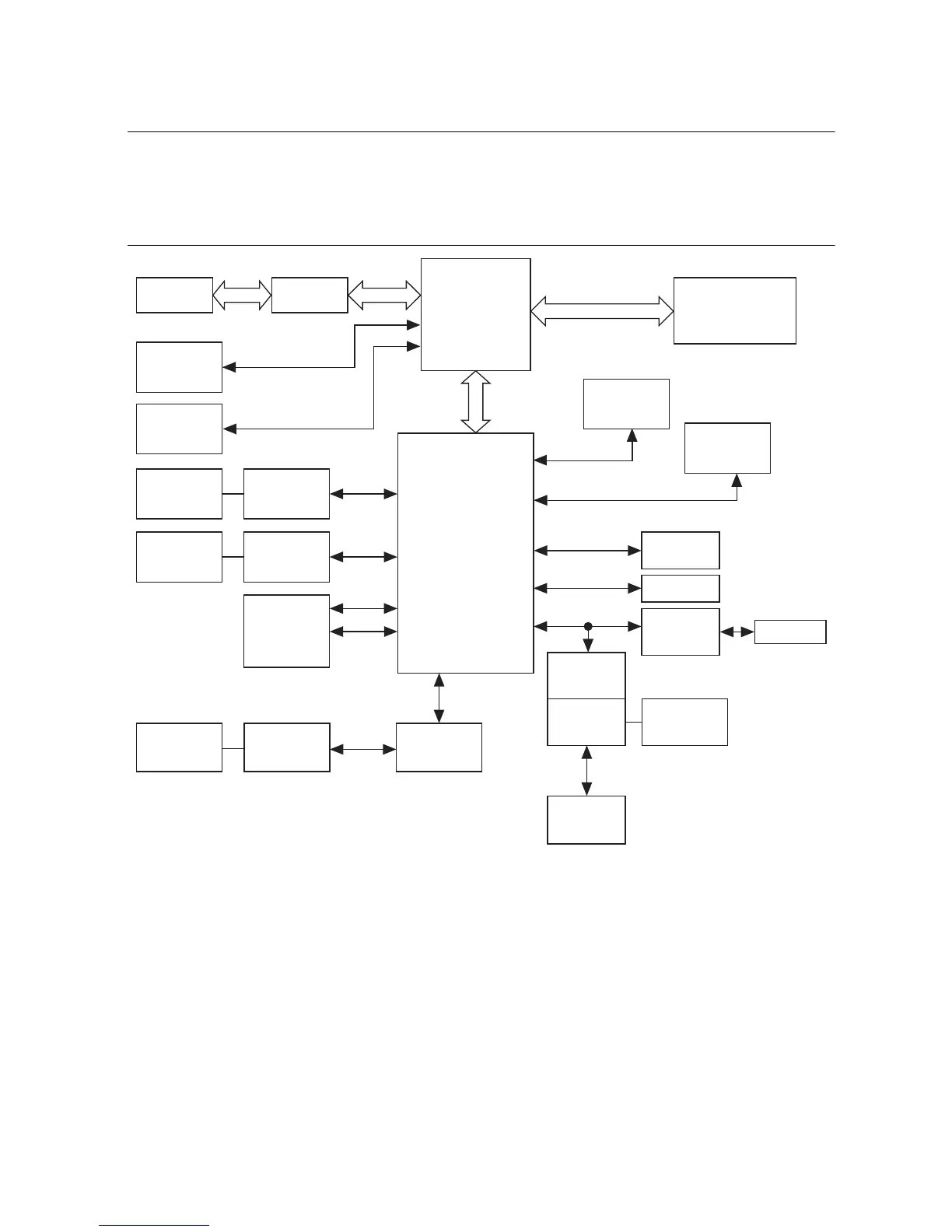
The PXIe-8840 is a modular PC in a PXI Express 3U-size form factor. Figure 1-1 is a functional
block diagram of the PXIe-8840. Following the diagram is a description of each logic block
shown.
Figure 1-1. PXIe-8840 Block Diagram
The PXIe-8840 consists of the following logic blocks on two circuit card assemblies (CCAs):
• The processor is an Intel
®
Core
™
i5 4400E processor (3 MB Cache, 2.7 GHz). The
processor connects to the SO-DIMM block through the DDR3L interface supporting up to
1600 MHz SO-DIMMs, the PCH through a x4 DMI2 (Direct Media Interface) interface
supporting up to 5 GT/s per lane.
• The SO-DIMM block consists of one 64-bit DDR3L SDRAM socket that can hold up to
8 GB of memory.
• The processor provides the DisplayPort interface that connects to display peripherals on the
PXIe-8840, and the PCI Express interface to the PXI Express backplane through a
PCI Express switch.
Intel
8 Series
PCH
Processor
Intel Core
i5
SO-DIMM
DDR3L SDRAM
PC3 12800
DisplayPort
Memory Bus Ch. A
Express
Card/34 Slot
(ExpressCard
Variant Only)
x1 PCIE
USB
USB 2.0 x4
SATA
Hard Disk
FLASH
Watchdog
Trigger
SMB
Connector
UART
COM1
x8
PXI
Triggers
GPIB
Controller
GPIB
Connector
USB 2.0 x4
Intel I217-LM
Gigabit
PHY
RJ45
Port 1
SATA
x4 DMI2
x4 DDI
LPC
PCI Express
Switch
PXI
Express
4x4
Intel I210-IT
Gigabit
MAC/PHY
RJ45
Port 2
x1 PCIE
SPI
PCI
DisplayPort
USB 3.0 x2
USB 3.0 x2
x1 PCIE
x4 DDI

 Loading...